yacht sale")


- Builder:
- CUSTOM
- Category:
- Motor Yacht
- Model Year:
- 2016
- Year Built:
- 2016
- Country:
- United States
- Cockpit:
- Yes
sales and service of boats, ships since 1959.
№1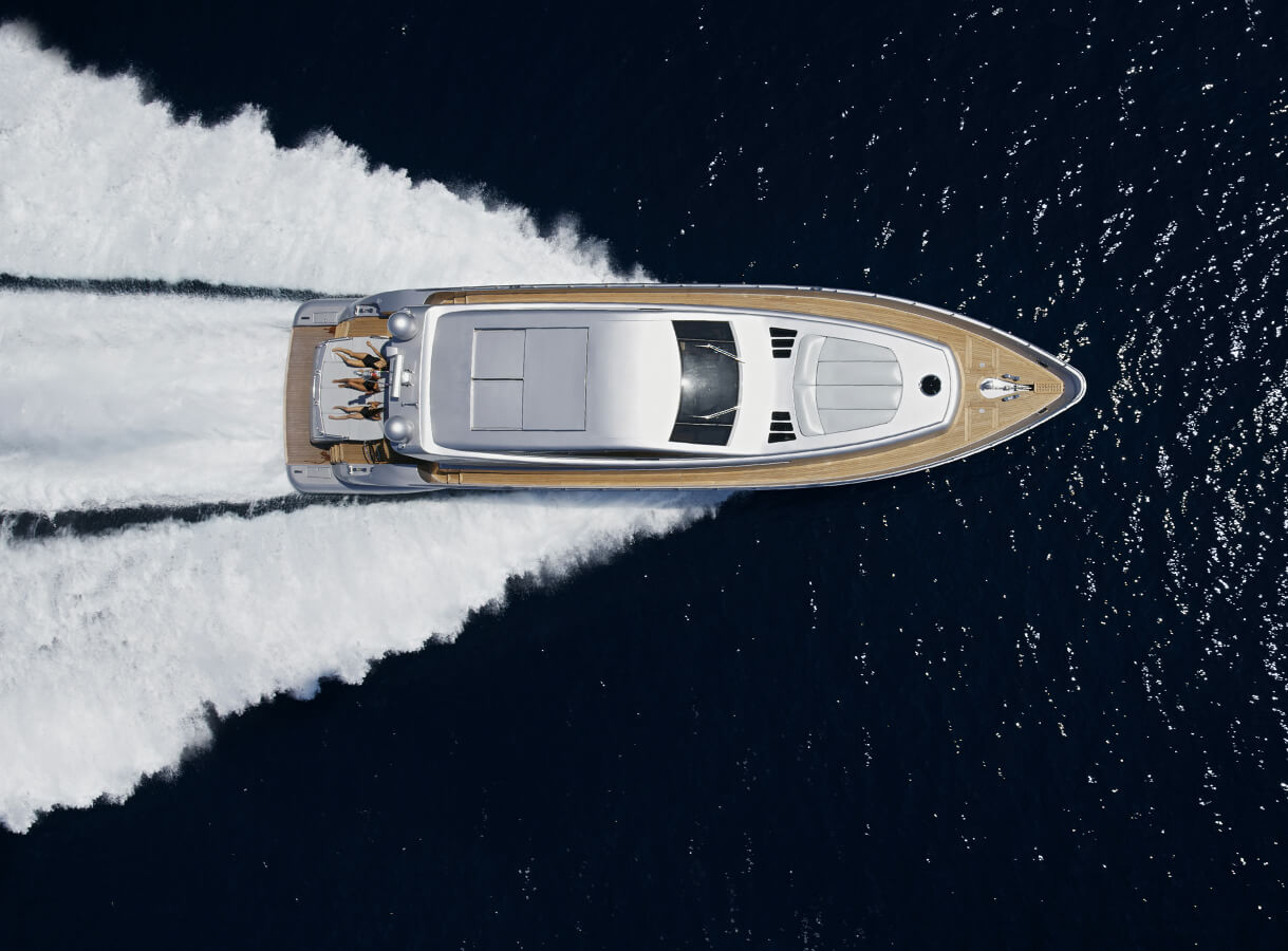
Unfortunately, this boat is not available for sale. It will be removed from the website soon.
CUSTOM - available for sale:
Yachts with similar parameters:


You can only expect new answers if you ask new questions. That was the basic idea that led to the development of the new Drettmann Motor Yachts, in which we took the usual as a starting point for the creation of something totally unusual.
As for the questions we asked: they fundamentally involved taking a critical look at what was already available. What do today‘s 20 to 37-metre yachts look like? What could make them look better and function better? And above all: how have the wishes and demands of the owners changed – and how do we consequently have to change our approach? Just a quick glance at the outcome immediately reveals that we came up with convincing answers to all these questions. One of the prime innovations is that the new lines have said goodbye to a classic design feature, namely the clear distinction between vol-uminous hull and superstructures.
Price shown is retail base price
1. General
The Vessel shall be a custom-developed planning hull constructed of FRP, built to operate for private use and for public charter in the Mediterranean and Caribbean seas in accordance with the design of Focus Yacht Design, Tony Castro naval architecture and the structural engineering of Rivoyre, Ltd., and in compliance with the rules and regulations published in the regulations of the Classification Society and with the Marine and Coastguard Agency (MCA) Code of Practice.
The Vessel's characteristics shall provide generous and luxurious accommodation spaces for theOwner's party, with good recreational deck areas, while maintaining a good level of sea keeping andperformance. The vessel will offer 8/10 berths in 4/5 cabins +crew accommodation for 4.
With reference to the level of finish and workmanship, the standard to be observed shall be the standard applied in fine European yacht building.
The crew's accommodation and working areas shall give the crew good comfort and will enable them to operate the Vessel effectively without unnecessarily disturbing the Owner's party.
The machinery concept is to achieve reliability by utilizing proven machinery and equipment from known manufacturers and utilizing industry standard modern materials and construction techniques to assure that future maintenance is obtainable in remote areas within reasonable levels.
The project is to be realised by a CNC cut female production mould allowing accost efficient production of multiple units. A high degree of customization is to be maintained to give the owner an individual package. Modular systems are to be developed to ensure production efficiency
This Specification preliminary one and will be continuously updated as the project evolves.
B. REGISTRATION
a) All fees and taxes associated to the registration of the Vessel shall be paid by the Owner.
C. BUILDER
The construction shipyard for this project is:
Arberger Hafendamm 22, 28309 Bremen, Germany
and
Sunrise Yachting Yatcilik Sanayi ve Ticaret, Ltd.
Antalya Free Zone, Antalya, Turkey
referred to as the 'Builder'.
D. NAVAL ARCHITECTS & DESIGNERS
1. Naval Architecture
referred to as the 'Architect'.
2. Engineering & Classification Coordination
referred to as the 'Engineers'.
3. Exterior and Interior Design & Styling
referred to as the 'Designers'.
E. CLASSIFICATION & CERTIFICATES
1. Classification
a) The vessel is to be built under the survey of and in full accordance with the Bureau Veritas Regulations for the Classification of Special Service Craft and including all Amendments and Notices issued up until the date of signing of the Vessel Construction Agreement.
b) The class notation shall be:
Yacht, MACH Charter Yacht, Motor, S ¡V Unrestricted Navigation to 60NM (short range)
2. MCA Certification
a) This vessel will comply with all of the requirements of LY2 - The Large Commercial Yacht Code Large for vessels 24 metres and over in load line length and the Code of Practice that applies to yachts which are in commercial use for sport or pleasure, do not carry cargo and do not carry more than 12 passengers.
3. Safety & Pollution Requirements
a) Construction will comply with all relevant COLREG and IMO regulations.
b) At completion, a MARPOL pollution and sewage certificate will be delivered.
4. Certificates
a) The following certificates shall also be enforced and/or supplied:
5. Country of Registry Regulations Cayman Islands, (Red Ensign) or at Owner's charge
a) The following rules shall also be considered, if required:
1. Construction - General
a) The components shall be built in accordance with high standards for FRP ship construction using
epoxy resins and technical fibres for local reinforcements and weight savings.
b) All parts of the hull shall be accessible for survey and maintenance.
c) Workshop conditions shall be in accordance with the requirements of the Classification Society.
d) The Builder shall also maintain a detailed log of the entire building process.
e) Materials shall be stored under conditions suitable to the Classification Society.
1. Main Engines Particulars
a) There shall be fitted with two four-stroke diesel engines of the following model:
2. Wheelhouse Instrument Panels
a) The wheelhouse room shall be equipped with electronic monitoring and control system.
B. GEARBOXES ANDPROPULSION
a) The gearboxes (ZF 4600V) are assembled in a V-drive configuration. Gearing and drive configuration to be determined in accordance with the Architect’s recommendations
b) A V-drive shaft configuration with 5 prong NIBRAL propellers supported by a set of P-brackets will be used. Water-lubricated no-drip stern tubes in composite construction shall be used.
C. CONTROLS ANDINSTRUMENTATION
1. Engine Controls
a) The engines and gearboxes shall be controlled by electronic controls by ZF – Smart command (CAN- bus)
b) There will be three stations:
D. GENERATORS
1. General
a) The main electric power is supplied by two diesel-driven, water-cooled generator sets.
b) For the electrical part of this system: see Chapter X, ‘Electrical System’.
c) The power of generators to be checked with the final electrical load analysis.
2. Generator Sets
a) All diesel generator sets shall be flexible mounted on a double set of hydraulic mounts or silent blocks.
b) All diesel engine driven generators to have hard-faced sound enclosures.
c) All generators to have a 24 V DC start system and an isolated ground.
d) Main Generator sets (2):
A. STEERING
1. Main Steering Gear
a) The rudders shall be actuated by means of a DATA HYD®or BCS®Class type-approved hydraulic steering system.
b) Rudder blades are to be fitted in accordance with the Architect’s calculation
c) Emergency steering as per class requirements are to be fitted
B. BOWTHRUSTER& STERNTHRUSTER
1. General
a) The Bowthruster & Sternthruster shall be hydraulic, running off the gearboxes’ P.T.O., with a control box in the ER compartment. The Thrusters shall have variable speed controls
2. Bowthruster & Sternthruster
a) The Builder shall install American Bow Thrusters (ABT / TRAC) hydraulic Bow- and Stern- Thrusters, rated power 65 HP (50 kW) and 16” diameter each, with proportional joystick controls at all three control stations.
C. STABILIZERS
1. Stabilizers
a) The Builder shall install an electro-hydraulic gyro-controlled non-retractable or partially retractable zero-speed fin stabilizer system by American Bow Thrusters (ABT / TRAC)
A. PUMPS
a) All pumps, where possible or otherwise specified, shall be from known suppliers
B. ANCHOR & MOORING SYSTEM
1. Anchor Windlasses
a) Two hydraulic vertical windlasses rated at 4.5KW kg pull Maxwell 4500. Maximum pull 3400KG
b) Gypsy kit for diameter 14 mm stud-link calibrated galvanized chain.
2. Anchors
a) 2 x 160 kg galvanized steel anchors “Delta”-type high holding power, (size to be Class approved) shall be provided and installed. The option of concealing the anchor pockets under movable covers is to be studied by the Designers
3. Anchor Chains
a) 2 x 137.5 m 14 mm diameter calibrated galvanized U2 stud-linked chain, to be located in chain
locker.
4. Chain Compressors
a) Two polished 316L stainless steel chain compressors to be mounted on base-plate on main deck.
5. Capstans
a) Two hydraulic vertical capstans of 1,000 kg pull each will be installed. Maxwell 2200
6. Mooring Equipment
a) Four mooring lines of 30 m each. 3 x 8 strand, 30 mm black square-braid Polyester.
b) Two mooring lines of 10 m each. 3 x 8 strand, 30 mm black square-braid Polyester with stainless
thimble/eye splice and a 2 m loop of 14 mm galvanized chain.
c) One 100 m sea towing rope of diameter specified by Class.
7. Fenders
a) Ten fenders, approx. 1000 x 400 mm, each with lines and fender covers (10 total).
b) Two fender-boards, each with lines.
C. FUEL SYSTEM
1. Fuel Transfer System
a) Fuel can be transferred to the running tank (gravity fed) via the following pumps:
D. WASTEWATER SYSTEM
1. Toilet System
a) JETS® centralized vacuum toilet system, with fresh water flushing and TECNICORMAR™ treatment plant.
b) The system shall be U.S. Coast Guard certified MSD type II.
2. Treatment Plant
a) Located in the engine / technical room, a TCNICORMAR® sewage treatment system will be installed.
3. Toilets
a) 9 toilets, JETS® model, for all bathrooms.
E. HYDRAULIC SYSTEM
1. General
a) The main hydraulic system will be for:
2. Main Hydraulic Power Pack
a) The main hydraulic system shall run all hydraulic equipment, including the stabilizers through a preferential valve.
b) The electro-hydraulic power-pack shall be driven by two 11 kW, 400 VAC, 3-phase, 50 Hz electric motors and a dedicated control box.
3. P.T.O. Pumps
a) The PTO hydraulic pumps shall power the bow thruster, the windlasses, capstans and the stabilizers while running. Selective valving shall guarantee operation of all equipment even if motors are not running.
F. CLIMATE CONTROL
1. Air Conditioning System
a) Compressor
a) The compressor units shall be CONDARIA®.
b) There shall be a 4 compressor units operating in sequence to provide tempered water for a chilled water line to the individual evaporators in each cabin.
c) The compressor units shall be Scroll-type 400 VAC, 3-phase, 50/60 Hz reaching a total combined cooling capacity of no less than 170 000 BTU
b) Fan Coils
a) Two fresh air makers shall insure the distribution all over the vessel of dry and pre-cooled fresh air
coming from outside the vessel.
b) The fan coils repartition shall be as follow (to be confirmed by the air conditioning supplier):
G. FRESHWATER SYSTEM
1. Hydrophore Pumps
a) There will be two G&R (GORMANN-RUPP)® , 400 VAC, 1 HP, water pressure pumps. A quiet operation will be assured.
b) One pressure accumulator tanks of about 100 l. (air chamber/diaphragm type), working/ test pressure 4/7 bar, will be mounted to keep the system pressurized.
c) Circulation pumps (hot and cold) shall be fitted
2. Hot Water System
a) The system to be fitted with two 220 l., 7Kw duplex steel hot water boilers, connected in series.
3. Water makers
a) One TECNICOMAR® water maker, with an total capacity of no less than 3000 litres per day, will be installed. 220V AC operation
4. Consumer Water Treatment System
a) Prior to being distributed to the consumers, the water shall pass through a freshwater treatment system, suitable for a fresh water flow of 2 m3 per hour.
b) The system shall consist of:
H. BILGE / FIRE FIGHTING SYSTEM
1. Pumps
a) There will be three pumps installed in the vessel to run the bilge and fire system:
2. Water-Mist Fire Extinguishing System
a) An automatic water mist extinguishing system with pressure pump and copper piping NOVENCO® XFLOW shall be installed throughout the accommodation of the vessel.
I. PNEUMATIC SYSTEMS
1. Low-Pressure Air System
a) One air compressors shall be installed in the engine room, pressure oil lubricated, air cooled. The working pressure is to be set at 10 bar to cut-in/out at (+-)5% to operate horns and transom door seals
2. High-Pressure Air System
a) The vessel will be fitted with an optional 400 VAC, 3-phase, 50-60 Hz, electrically-driven BAUER®
dive compressor.
J. LUBE OIL SYSTEM
1. Oil Transfer Pumps
a) Oil change system for both main engines and generators with two reversible pumps such as an G&R® or equal 1/2 HP, 230 VAC and manifold and all necessary plumbing. As prescribed by class.
K. DOMESTIC APPLIANCE SYSTEMS
1. Main Galley Appliances
a) Two LIEBHERR® stainless-steel refrigerator/freezers, stand-alone type.
b) One four-burner GAGGENAU® electric induction cooking range.
c) One custom stainless steel exhaust canopy with fire extinguishing system.
d) One GAGGENAU® or similar cooking oven.
e) One GAGGENAU® or similar microwave oven.
f) One MIELE® or similar professional dishwasher.
g) One Trash compactor
h) One Deep freezer chest
2. Owner’s Appliances
a) One ULINE® or similar fridge in owner’s cabin and VIP cabins (option)
3. Flybridge Appliances
a) One FOSTER® or similar icemaker.
b) One LIEBHERR® or similar under-counter fridge.
c) One Double Grill BBQ, JENN AIR® or similar.
4. Beach Club Appliances
d) One FOSTER® or similar icemaker.
e) One LIEBHERR® or similar under-counter fridge.
5. Pilothouse Appliances
a) One ULINE® or similar fridge in the pilot house
6. Laundry Room Appliances
a) One MIELE® or similar commercial washing machine or 2 smaller capacity units
b) One MIELE® or similar commercial dryers or 2 smaller capacity units
c) Central vacuum system with outlets in all cabins
L. ENGINE ROOM VENTILATION
1. Main engine extractor fans
a) Two extractor fans operating at 220V located in the aft quarters of the engine room side walls (PORT, STBD)
b) Two forced air blowers of sufficient capacity located on the forward engine room side walls (PORT,STBD) The blowers are to be dimensioned to create a slight over-pressure in the engine room even during high speed running.
c) The air intakes and extractors are to be fitted with a remote control shut-off valve to completely close off oxygen supply to the Engine room in case of fire.
A. GENERAL a) The Vessel¡¦s main power supply shall be a 240/400 Volt, 50 Hertz three-phase four-wire system with neutral grounded, based on a split-bus distribution circuit. b) The vessel will be controlled and monitored by a Yacht Control & Management (YCM) system. c) The electrical power supplies on board are based on:
B. SHORE POWER SYSTEM 1. General a) Shore power cables shall be provided P/S aft in the garage. They will be accessible from outside with powered reels for extraction and retraction of the cables. b) Care will be taken to ensure that all cables are routed from the shore so as avoid obstruction on deck or to the gangway. c) These cables will be connected to a 75 kVA shore power converter that will act as a galvanic isolation transformer as well as a frequency converter. d) Controller unit shall be installed in a clean, dry space. 2. Frequency Converter a) The frequency converter shall be an double-input with a maximum output to a single bus of 75 kVA, 400 VAC, 3-phase, 50 Hz. 3. Shore Power Cable a) 1(one) 100-foot (30 m) HUBBELLR type / 125 Amp./ 125 -250 V, 4-wire Ship to Shore cord. 1 backup unit (not connected to the reeling mechanism) shall be provided. b) Plugs receptacles and adapters, to accommodate 125 Amp. single (1) or three (3) phase power. c) A Cable Master shore power cable reeling system shall be installed C. POWER CONVERSION EQUIPMENT 1. Battery Chargers a) There are two 100 Amp battery chargers, MASTERVOLTR Mass 24-100 or equal, with a manual change-over system for changing wires. One back ¡Vup 70 Amp unit shall be installed. This will enable charging of all battery banks to take place with backup in the event of one of the chargers failing. Uninterrupted Power Supply (UPS) a) Local UPS will power the following units :
b) These UPS to be powered off the ship's main power. D. YACHT CONTROL & MANAGEMENT SYSTEM a) A YCM system consisting of two dedicated automation processors, working in mirror, and a set of required interfaces all linked together by a data bus is installed on the vessel. b) The purpose of this YCM system is to control and monitor the entire vessel. c) All the equipment used for the YCM system is Class Approved and manufactured by Boening E. ALARM, SAFETY ANDWARNING SYSTEMS 1. Systems Central Alarm a) The YCM system will be the central unit of the alarm system on board. 2. Burglar Alarm a) A burglar alarm shall be fitted and is included in the electronics package. |
Electronics VII. ELECTRONICS A. COMMUNICATION 1. SSB Transceiver a) One FURUNOR MF/HF 5000 SSB, 150W, GMDSS approved, automatic antenna tuning unit fitted with automatic and manual grounding system. 2. VHF Transceiver a) Two FURUNO R VHF RT 5022 with DSC Class A, one remote in the crew mess and the other at the chart table, Wheelmark approved. 3. Cellular Phones and portable sat.Phone a) Two ERICSSONR, or equal GSM base station phones with their own 24VDC/12VDC power reducer. They will be connected to the vessel¡¦s PABX system. b) One THURAYA R portable Satellite phone will be provided 4. Handheld VHF a) 3 SIMRADR, Axis 50, handheld GMDSS VHF waterproof made and fitted with a multi desk quick charger. 5. Fleet Broadband Station a) One SAILORR 250 Inmarsat Fleet Broadband station with a dedicated fax , a emergency push button, connected to a GPS NMEA output, providing a connection to the telephone distribution and allowing data transmission. 6. SAT TV ¡V Internet One SEATELR 2004 TV-at-Sea satellite receiver with European LNB. 7. Inmarsat-C Station a) One SAILORR TT-3000EB Mini-C with GPS-option GMDSS Inmarsat C station with H-1252 dedicated printer. 8. SSAS a) One SAILORR SSAS add-on kit with Alert & Test buttons. 9. Safety Transponders See Chapter: XII.1.3 EPIRB & SART 10. Telephone Distribution a) One PANASONICR or LGR PABX connected to the Fleet Broadband, the VSAT, cell phone units and shore connection when available. B. NAVIGATION ELECTRONICS 1. Differential GPS a) One SIMRADR MX500 DGPS receiver with differential facilities connected to the NMEA interface. b) One SIMRADR MX 510 GPS receiver shall be fitted as a back -up 2. Navtex a) One FURUNO NX 700 DPROB Navtex receiver with active antenna. 3. AIS / Longe Range IT Transceiver a) One FURUNOR FA 150P AID station transceiver connected to the NMEA interface. b) One FURUNOR Felcom 16 LRIT station transceiver connected to the NMEA interface. 4. Navigation Computer/Plotter a) SIMRADR NSO Glass Bridge navigation system to be as follow:
5. Navigation Instruments (see Nav. Instruments non-electronic)
6. Echo sounder a) One echo sounder SIMRADR BSM01 interface. 7. Radar a) One FURUNO R FR2117 Radar, 12 kW, 72 Nm fitted with 6ft. scanner unit shall be connected to the gyro compass and GPS NMEA output via chart plotter GB40. 8. Log/Speedo a) Included in Navigation Computer. 9. Autopilot a) One SIMRADR AP50 IMO/Wheelmark automatic pilot connected to the gyro compass and NMEA interface. b) A NMEA switch by software or hardware shall be provided for using either GPS NMEA output or marine navigation software NMEA output. c) The output signal will drive the main steering system. 10. Gyrocompass a) Regular SIMRADR GC80 gyrocompass with sin/cos, Cif and step by step interfaces. b) A rudder feedback unit and a remote control display shall be provided. 11. Navigation Software a) One SIMRADR GB40 navigation software with NMEA and radar overlay interfaces. 12. Rudder Angle a) An IMO-approved SIMRADR AR78 independent steering repeater system shall be installed on the main rudder tiller. b) Indicators at each steering station. 13. Antennea Requirements a) Antenna layout arrangement to be defined as per supplier¡¦s specifications. C. NAVIGATION, NON ELECTRONIC a) One (1) RIEKERR Instrument RIE-2055 inclinometer. b) One CASSENS & PLATHR or equal magnetic compass to be fitted in navigation area according to Classification Society rules. D. ENTERTAINMENT 1. Central Rack & A/V Server
2. Crew Quarters
3. Owner's Accommodation
4. Guest's Accommodation
5. Main Deck Salon
6. Aft Main Deck
7. Sun Deck / Flybridge / Beachclub
8. Foredeck Area
9. CCTV
10. Computer Network
11. Shore Connection a) The following shore connections to be provided:
|
Exterior Outfitting VIII. EXTERIOR OUTFITTING A. WOOD JOINERY EXTERIOR 1. Teak Decks a) Teak deck planking 12mm x 50mm finished dimensions, glued to deck with SIKAFLEXR or equal. B. DECK EQUIPMENT 1. Windscreen Wipers a) ThreeSPEICHR or equal windscreen wipers, variable speed, 24 VDC with 40¡¨ wiper blades shall be fitted to the forward windows of the wheelhouse. 2. Passarelle a) A 6 m long electro-hydraulic gangway (minimum width 700 mm), in the same style as the accommodation ladder, exiting through a flush door in the transom. 3. Boarding Ladder / Royal stairs a) A stair boarding ladder shall be provided. b) Royal stairs for side boarding on the STBD side shall be provided as an option 4. Swimming ladder a) The swimming ladder shall extend approximately one meter down into the water and have comfortable 600 mm wide teak steps. 5. Flag Pole a) On centerline, a 316 L stainless steel flag pole 2 m-long of sufficient diameter in a support integral with the aft side of the bridge deck bulwark. C. TENDER & JETSKI GARAGE 1. General a) The tender garage at the bow will accommodate one tender up to 4.5m length (Jet driven ¡V Williams or similar) b) The jetski garage at the stern next to the beach club will accommodate one jetski D. INVENTORY 1. Deck Equipment a) The Builder shall include provisions for storage, hoisting or deployment of the following Owner Supplied Items:
|
A. PAINT SYSTEM 1. General a) The entire painting system shall be BASF |
A. GENERAL
1. Life Rafts & Equipment
a) Two (2) SWITLIKR, DPSR, VIKINGR orsimilar life rafts to be supplied by the Builder as per Class and SOLAS regulations for a vessel of this size.
b) Four ring buoys stored in recesses with vessel identification as required by SOLAS.
2. EPIRB & SART (Owner's Supply)
a) One SIMRADR EG50 Type I EPIRB with hydrostatic release and deck mount casing;
b) One SIMRADR EG50 Type II EPIRB, bracket-mounted in the wheelhouse;
c) One SIMRADR SA50 Search and Rescue Transponder.
3. Flares
a) The following equipment is to be supplied with the Vessel in accordance with governing authorities:
4. Fog Horn
a) One chrome plated KAHLENBERG„µ marine air horn system, D2 model with M511A fog signal timer, according to Classification Society and Flag Registry rules.
5. Searchlights
a) One Xenon searchlight shall be mounted on the mast with remote control at the helm in wheelhouse.
6. First Aid Kit
a) A first aid kit, suitable for a world-wide cruising motor yacht of this size, according to SOLAS and Lloyd's is to be supplied.
7. Life Vests and Harnesses
a) 24 life vests, with radar and light reflectors, will be supplied with the vessel in accordance with SOLAS, Class and U.S Coast-guards regulations.
b) A whistle and stroboscopic light will be delivered for each life vest.
8. Fire Alarm System
a) A general fire alarm system fully in accordance with the statutory- and class and requirements shall be installed.
b) The system shall incorporate:
9. Accommodation Fire Prevention
a) A NOVENCOR XFlow. or equal automatic water mist extinguishing system shall be installed on the vessel.
10. Fire hoses
a) Five fire hoses shall be housed in deck lockers in the direct vicinity of the STORZR valves, connected to the fire main:
Each hose shall be fitted with a dual purpose nozzle and shall be stored in a non-corrosive rack.
11. Misc. Fire fighting Items as per class requirements