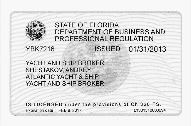
- Builder:
- H2X YACHTS & SHIPS
- Category:
- Catamaran
- Model Year:
- 2010
- Year Built:
- 2010
- Cockpit:
- Yes
sales and service of boats, ships since 1959.
№1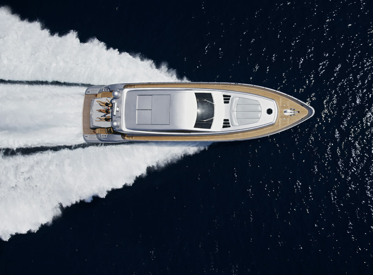
Unfortunately, this boat is not available for sale. It will be removed from the website soon.
Yachts with similar parameters:


New construction
A new and unique design to achieve unequalled goals of perfection, performance and space.
Number one under construction for sale.
Conception : NAHEMA
Naval Architect : Gilles VATON / BGV
Interior Designer : Frank DARNET Design
Structural calculations : Rivoyre Ingénierie
Builder : H2X Yachts & Ships (La Ciotat - FRANCE)
Type : World fast cruising Catamaran
Construction : E-Glass & Carbon / PVC / Epoxy Composite infusion Process
Conception according to C.E certification.
Construction to Bureau Veritas class rules and to comply with the code of practice for safety of large commercial sailing & motor vessels (MCA).
These rules give to the Nahema cat 120’ important guarantee in term of :
- security,
- structure stiffness,
- stability,
- handling security,
- fire fighting, environmental Protection & pollution prevention.
Length overall : 35.00 m / 115’
Length waterline : 32.38 m / 106’
Beam : 14.32 m / 46’
High overall : 46.50 m / 153’
Minimum draft : 1.80 m / 5.9’
Maximum draft : 4.50 m (centreboard down) / 14.8’
Engine : 2 x 500 HP CUMMINS
Generators : 2 x 40 KVa
Fuel : 2 x 8.000 ltrs plus 2 x 300 l (daily tank)
Fresh water : 2 x 3.000 ltrs
Water maker : 2 x 350 l/h
Grey water : 2 x 1.000 ltrs
Black water : 2 x 1.000 ltrs
Main sail (fully battened), 3 reefs: 376 m²
Yankee: 257 m²
Stay sail: 135 m²
Option Code 0: 620 m²
The sails are made out of composite cloth composed of Vectran fibres in between anti UV Mylar films.
Fibres are oriented and converge to the sail points where max loads are concentred.
Sails can be made out of Cuben Fiber as an option.
FLYBRIDGE
- Teak deck in the cockpit
- Flybridge cockpit surface: 16 m²
- Sunbathing surface: 9 m²
- Access by two stainless steel stairways with teak steps
- Watertight companionway access to fly bridge
- Four scupper drains
- Sunbathing area with cushions & mattresses, coffee table, frigobar, Hifi & video
- One lift for drinks & appetizers from saloon bar to flybridge
- Light under the boom
- Awning integrated into the boom
- Two steering stations protected by permanent light Biminis including full navigation equipments, engine & hydraulics controls
- Deck sailing hardware (winches, blocks & jammers) on the top roof close to the helm stations
- Storage lockers.
- One carbon varnished flagstaff, complete with halyard is installed at the aft end of the fly bridge.
AFT DECK
- Teak deck in the cockpit & aft deck.
- Surface: 61 m² (including aft cockpit, sunbathing area, spa & aft deck).
- Spa pool with sliding hatch integrated in aft deck.
- Integrated rolling curtains in the aft rooftop.
- Dinning table, sitting area & armchairs for twelve guests.
- Deck Cushions & mattresses.
- Large deck lockers with teak planked flush deck hatches on cockit floor.
- Sliding door main access to saloon.
- Hydraulic stern lift platform for main tender haulage. Surface 21 m².
- When the tender is launched, the tender lift become a bathing platform fitted with a shower, stainless steel bathing ladder and a submersible swimming pool system fitted with side nets.
SIDE DECK & FOREDECK
- White non-skid Awl Grip paint.
- Side deck & foredeck area: 2 x 54 m² = 108 m².
- Two trampoline nets (surface: 45 m²) are lashed between the hull, forward crossbeam & compression beam.
- Twelve flush deck hatches custom composite made on each hull with gas struts.
- Two sliding hatches for access to the forward crew cabins.
- Diesel & water fill fitting in dedicated lockers.
- Pump out deck fitting for black & grey water in dedicated lockers.
- Two custom-made stainless steel pulpits with teak seat & navigation lights.
- Two custom made stainless steel stern pushpits.
- Stainless steel stanchions with three stainless steel rod lifelines.
- Two gates in the lifeline railing on the port & starboard side situated amidships.
- A hull wash system is integrated to the hull at the sheer line level.
LAZARETTE & STERN DOORS
- Two opening Stern doors providing access to two stern garages for the crew tender, jet ski and Diving equipments.
- One retractable stairs in way of deck access.
- Two hydraulic telescopic gangways fitted with a tender launching system.
ROOF
- The roof is divided by a corridor allowing an access from the fly bridge to the mast step area and the forward deck.
- One opening flush deck window (6 m²) allowing light and natural ventilation to the main saloon.
- Window and windscreen in tempered laminated tinted glass.
- One windscreen wiper at the navigation area.
- The whole windows are fitted with Oceanair venitian blind system.
- White Awl Grip non-skid paint treatment on top of roof.
- Light all around the roof.
CENTERBOARD SYSTEM
- Two asymmetric composite centreboards.
- The two centreboards are retractable by a built in hydraulic ram.
STEERING SYSTEM
- Two semi-balanced aerofoil sections made out of carbon / PVC / Epoxy sandwich over stainless steel rudderstock.
- Two self-aligning rudder shat bearing on each side – make JP3.
- Hydraulic steering ram system provided by electro hydraulic unit situated in the lazarette.
- Manual steering is provided to the wheels at the fly bridge steering station through two hydraulic manual pumps integrated in the pedestal.
- Steering provided through a joystick at both steering stations and one joystick at the navigation station. Each steering position fitted with a rudder angle indicator.
- Two custom carbon wheels at the fly bridge.
- Two autopilot providing control of the steering via the electro-hydraulic unit.
- One autopilot heads at both fly bridge helm position and at the navigation area.
- Two retractable hydraulic bow thrusters Type Max power R 300 with proportional control stick at both the fly bridge helm stations.
ENGINE ROOMS
- The two engine rooms (30 m²) are situated amidships. The access is through two doors in the corridor between the forward and aft cabin.
- Engines rooms are divided in two levels (0 & 1) fully sound and heat insulated.
- The lower compartment (level 0) includes the main engine, the pumps, water heathers, the hydraulic unit etc…
- The technical room (upper compartment level 1) includes the generator, Electric
- Distribution panels AC / DC) , Bilge manifolds, Watermaker, Air conditioning unit, Battery chargers, inverters…).
- There is one 300 litres fuel daily tank fitted with an automatic and manual filling system in each engine room.
INSULATION
- A special study has been carried out to ensure that the construction of the vessel and the installation of the equipments met the objective of low levels of noise and vibrations.
- Engine and the technical rooms are fully insulated using fire resistant materials with a central rubber mass layer in order to assure both thermical and acoustical insulation.
- All motorised equipments are elastically mounted to reduce vibration.
- Exhaust & ventilation fans are properly selected and fitted with silencers.
- Flexible mounting and insulation of bulkheads, ceiling and floors.
- The engine room’s floor plating are elastically mounted.
- The accommodation « modules » are flexible mounted.
VENTILATION
- Each engine room are forced air supply through:
- One 4000 m3/h/ 380 VAC variable speed axial fan.
- Ventilation ducts fitted with water traps and baffles.
- The ductings are provided with fire dampers, shut off valves and mist eliminator operated from outside the engine room.
- The engine air extraction is provided with one 2000 m3/h helicoïdal extractor fan.
- A forced ventilation system (VMC) is installed to assure good ventilation in all living areas.
- Particular care is given to natural and forced ventilation throughout the vessel especially in heads & bathroom.
- The galley fumes are extracted by a high capacity speed adjustable fan hood fitted with flames resistant filters.
PROPULSION
The propulsion system is a twin engine, variable pitch propeller system allowing an higher propelling output and optimized speed performances and thrust.
Main engine
- The system is designed with a « manoeuvring » mode in which the engines run at a
constant Rpm with ahead / astern manoeuvring provided by the variable pitch
propeller control.
- The propulsion system is provided by two diesel engine of 500 CV at 2100 rpm.
White painted
- Engines are fitted w ith a driven bilge pump with an electro magnetic clutch.
- Engines controls are electrical and are situated at the three helm positions.
- Engines are fitted with auxiliary drive for alternators (175 amps) to charge the service
batteries bank.
- Engine mounts are specially calculated in order to reduce vibrations.
Gearboxes
- The gear Boxes suitable for the pitch controlled shaft line are rigid mounted on the vessel structure and connected to the engines by a flexible coupling.
- Gear boxes are equipped with seawater cooled heat exchangers, lube oil pumps, electric transmission control.
- Gearboxes include a thrust bearing taking the propeller thrust straight to the hull in order to reduce vibrations.
Propeller & shafting
Twin hydraulically controlled feathering propeller units comprising:
- One stainless steel hollow shaft diameter 100 mm including the pitch control rod connected to a hydraulic ram.
- Foor blades CUNIAL propeller with moderate skew back, diameter 950 mm
- Lubricated propeller hub.
- Pitch control unit, complete built-on EL control, consisting of 24 VDC motor.
- Four manual control indicators, one in the machinery space, one at the navigation area and one at each flying bridge helm station.
GENERATORS
The main electric power is supplied by:
- Two diesel driven, water cooled generator sets 380 VAC, 50 Hz Northern Lights 40 Kw generators installed into the technical room.
- One generator 380 VAC, 50 Hz Northern Lights 15 kwa installed in the port technical room to allow air conditioning and cooling systems to run at night.
- Generator sets are mounted on hydrolastics vibration mounts inside high efficiency sound shield.
- The generators will have separate 24 VDC battery banks of 120 AH Sonnenschein.
- Each generator to have 55 Amp: 24 V alternator.
- Operations of Ac power supply is performed by means of a manual starting, paralleling, load sharing and stopping system.
- Automatic disconnecting management of selected consumers in case of overload of the generator.
- Engine starting & stop circuit will be 24 VDC via push buttons from engine control console, from local watch panel.
- There is a Manual stop from the emergency switchboard in the technical room.
SYSTEMS
- The whole of the systems is studied in a way of simplicity and good access for maintenance and repair.
- All systems are designed and installed according to Bureau Veritas.
- All motors, pumps and others equipments and machinery are installed on flexible mounts.
SANNITARY SYSTEM (Black Water)
- The sanitary system is based on a hammam sewerage treatments system to provide for zero discharge of both grey and black water in sensitive environmental areas to comply with the U.S coastguard standards.
- Discharge to holding tanks (total capacity: 2000 l) fitted with inspection hatches, vent and odour filters.
- The tanks have an electronic level control, with calibrated alarm linked to the ship’s main alarm panel.
- The holding tanks are emptied by their own diaphragm-type sewage transfer pump through an automatic & manual operation mode.
- Black Water tanks is also connected to the 220 VAC pump manifold for back-up discharge.
- The pump discharge to deck fitting located on deck in a recessed tank-fill box.
- Eight Electric toilets to flush with freshwater, 24Vdc.
SUMP SYSTEM (Grey Water)
- The used water from lavatory sinks, showers, washing machines, and dishwasher are collected into grey water tanks (total capacity 2000 l).
- The grey water may be directed into the grey water tanks or diverted into the black water tanks to be processed by the sewerage treatment units.
- The tank will have an electronic level control with a calibrated level alarm linked to the ship’s synoptic panel.
- The tank share the on-deck discharge connection, via a three-way valve, with the black water discharge.
- Each tank will have its own discharge pump, a self priming diaphragm type make 1.500 l/hr.
- Tanks level are connected to the general monitoring system.
HYDRAULIC SYSTEM
- The hydraulic system is based on the ring main principle, where all hydraulic functions onboard, except the steering system, are connected to a common piping system running throughout the vessel. It will comprise of the following:
- One PTO on each generator driving a pump at 50 Kw.
- One 24 VDC powerpack of 15 Kw fitted with a 200 litres tank.
- All on board hydraulic equipment will be driven by the system to run the following functions:
- 2 x warping winches on the fore decks
- 2 x warping winches on the aft decks
- 2 x anchor windlasses
- 2 x furling units (Genoa & staysail)
- 2 x retractable thrusters
- 10 x winches
- 1 x tender lift
- 2 x lazarette doors
- 2 telescopic gangway
- 2 tender launch system
- 1 x vang
- 1 x main sheet traveller ram
- 1 x main sheet ram
- 2 x headsail and staysail halyard rams
- 1 x flattener
- 1 Cunningham ram
- A double constant flow type electro-hydraulic power pack Lecomble & Shmidtt dedicated to the steering system and autopilot.
- A Multifunction manual hydraulic control panel pump for sail trimming with pump pressure gauge and selection valve located in the fly bridge cockpit.
FRESH WATER SYSTEM
- Two 3000 litres fresh water tanks built out of composite panel in the hull bottom structure. Pressure tested at 0.5 bars.
- Filling stations on deck have stainless steel, "Water" engraved screw on caps.
- Fresh water tanks fitted with level indicator to gauge on the synoptic panel. The tanks capacity can be read-out on an electronic display at the navigation station control panel.
- Two 350 l/h modular watermakers (HEM) are located in the technical room.
- Fresh water distribution throughout the yacht is produce by two hydrophore pumps 24 VDC pressure set fitted with 50 litres of accumulator tank via UV sterilizer.
- Two stainless steel hot water boilers, 200 ltrs /2 Kw. each, connected serial.
- The hot water is supplied to the consumers via an insulated ring line to provide instant hot water at each outlet.
- There will be a silver sterilization unit fitted to process both dock water and water maker water.
- Taps & faucets to be define by owner.
- Four fresh water outlets fitted with quick connectors on deck for deck showers, and deck wash.
- One outlet for the windscreen wiper + one hull wash system alongside the hull sheer.
BILGE SYSTEM
- A combined system with three ways valve is installed for bilge and fire fighting.
- Each bilge area has individual bilge suction lines led to a manifold in the technical rooms for easy operation.
- The system includes 4 types of pumps for each hull located in the engine room:
- one Engine-driven pump, 18 m3/h. with an electro magnetic clutch.
- one centrifugal 230/400 VAC pump: 90 gpm at 3,5 metres,
- one centrifugal 24 VDC 18 m3/h.
- one diaphragm pump dedicated for the engine compartment.
- The 380 Vac. and the engine-driven pump are connected in parallel via a manifold.
- All bilge sumps are equipped with a bilge alarm, parallel connected to the central alarm unit.
- An emergency fire and bilge pump is located on the main deck.
- Every watertight compartment are fitted with an automatic submersible dewatering ump activated by a float switch, this same float switch shall be connected to the alarm/monitoring system.
FIRE FIGHTING SYSTEM
- The main bilge pumps will also supply pressure to two Fire/deck stations with an effective fire-fighting stream.
- Fire hydrants fitted with international fire fighting connections are permanently fitted on the main deck (port & starboard).
Engine Room Fire Fighting System:
- The engines rooms are protected by an FM 200 inert gaz extinguishing system, with the adequate amount of nozzles.
- A release handle is situated outside the engine room.
- Appropriate fire extinguishers are located throughout the vessel spare in accordance with MCA regulations.
ALARM SYSTEM & MONITORING
- A central organised fire/smoke detection system with alarm is fitted in the navigation station.
- Fire & smoke detectors is installed in each vessel’s compartments, with audio/visual alarm and display panel at the navigation station.
- A strub light is installed in each engine room.
- There is a custom-built comprehensive PLC monitoring, alarm and controls system.
- This will have five large colour waterproof touch screens located in the:
- engine rooms,
- navigation station,
- fly bridge helm stations.
- The system is capable of monitoring, controlling and displaying information at each helm stations as follows:
- main engine and generator revolution (rpm),
- smoke dedectors,
- bilge high level,
- black & grey water tank high level,
- fresh water tank low level,
- fuel tank law level.
COOLING & FREEZING SYSTEM
- All refrigeration is by 380 VAC compressors, each linked to its own dedicated evaporator plate in either the refrigerator or the freezer.
- Compressors mounted in the technical room are seawater cooled and are equipped with their own cooling fan.
- Compressors will be seawater cooled.
- All refrigeration cabinets are stainless steel custom made to fit and match interior design.
- The vessel will be equipped with:
- Two cold rooms (positive and negative) for food storage located in the galley. Isolation polyurethane sandwich 100 mm /M1.
- Each cold room fitted with outside thermometer for constant monitoring.
- Two positive refrigerated bars for drinks and cold preparation storage located in the galley.
- Frigo bar and icemaker located at the fly bridge and the main saloon bar.
- One frigo bar and in each guest cabin.
- Two wine cooler cabinets.
- One cigar cooler cabinet.
AIR CONDITIONNING SYSTEM
- The vessel will be fully air conditioned in the interior through two reversible chilled water central units 380 VAC, 50 Hz power.
- Capacity 200 000 BTU.
- Fresh air is brought into all living quarters through fan coils units.
- Air supply grills and thermostat control are integrated in the accommodation in each area to be climate controlled.
- Temperature is adjusted in each individual room by remote control, independently of their neighbours.
- Cabin thermostats for all spaces will have Summer/Winter switchover.
FUEL SYSTEM
- Total capacity: 16000 litres in 4 x 4000 litres structural composite tanks + two daily tanks of 300 litres.
- Manholes are fitted to perform tank cleaning. Each tank has a low point cleaning valve.
- The fuel is lead via valves and a manifold to a 24 VDC transfer pump, 1500 litres/h.
- One fuel counter unit as part of the transfer system.
- One manual transfer pump.
- Manual shut off outside the engine room.
- The main engine and generators are feed via a manifold from the day tanks and via a RACOR Duplex Filter with suction / pressure gauge.
- All four fuel tanks will be fitted with level gauges and sight glasses.
- Fuel flow will be measured for each engine and displayed via the monitoring system.
- Anti bacteries filters.
- In addition, there is an additional RACOR Duplex filters with suction and pressure gauges between the fuel transfer pump and the fuel day tanks.
- The transfer manifold allows fuel transfer between all tanks.
ELECTRIC SYSTEM
- The electrical power supplies on board is based on:
- 380/220 VAC/50 Hz, three phases with grounding neutral supplied from a combination of two identical Northern lights generators at 40 Kw.
- One 40 Kw shore Power converter.
- One shore supply socket fitted with a shore supply cable 50 metres long, 125 amps.
- Five Sonnenshein gel type 24 Volts DC batteries banks as follows:
• Generators starting battery: 24 V / 120 Ah
• Main engine starting battery: 24 V / 200 amp
• Service battery: 12 x 2 volts elements / 1500 amp
• Emergency battery: 24 V / 500 amp
• Radio battery: 24 V / 200 amp.
• Battery banks are placed in the technical room.
• All battery banks will be alarmed for high and low charge status.
- All electrical equipment, wiring, cables, fixtures and the complete installation are in accordance with good practice and High quality ships wiring cable are used on all power distribution circuits.
- All cables are sized in accordance with manufacturer’s recommendations and BV regulations.
- All distribution and control circuits are protected by high sensibility magneto-thermical / bipolar circuit breakers.
CHARGING SYSTEM
- Each batteries bank will have is own charging system.
- Charging of the battery banks is achieved from generators and main engine alternators as follows:
- One x 175 amp on the main engines to charge the service battery bank.
- One x 55 amp alternators on the main engines to charge the start batteries.
- One x 55 amp alternators on the generators to charge start generator batteries.
- Charging will also be achieved via the following battery chargers fitted with temperature sensors:
- The navigation / emergency aid batteries will be charged through two chargers 24 V / 100 amp.
- The service battery banks will be charged through three chargers 24 V / 100 amp.
INVERTERS
- The inverters sine-wave type are fitted for navigation, communication, stereo equipment and lighting as follows:
- One sine-wave inverter 24 / 220VAC, 3 Kw, will be located with the emergency aids batteries, to allow every emergency operation.
- One inverter 24 / 220VAC, 6 Kw, for lighting constantly drawing off the service battery bank.
- Two 6 Kw inverter 24 / 220VAC, 6 Kw, for the rest of the AC requirements when the boat is in quiet ship mode.
DISTRIBUTION PANELS
- The generators and shore power supply are connected to a split bus bar system.
- Power on these bus bars is then distributed through a Main switchboard located in the technical room. This main switchboard manage the AC power supply.
- Power is then distributed through a distribution panel located at the navigation station with all the protection for the secondary distribution board located in every main area of the vessel with all protection for domestic lines.
- In addition there is a Domestic panel located in the galley with all main controls.
- DC power from the battery banks go to the DC distribution board, which is located as near the source as is possible to avoid voltage drops.
Main switchboard/control centre:
- The main switchboard will be located in the technical room.
- Main switchboard has a fully electrically and mechanically interlocked power source control panel for:
• Two on board generators.
• Shore power line.
• All feeds can be isolated at the panel.
AC DISTRIBUTION PANEL
- Contained in these panel are switches and all the relevant two poles circuit breakers, voltage, intensity and frequency of both generators and shore power.
- The entire cabinet is hinged to give easy access to all circuit breakers from behind.
- Secondary pannels include all protections and relays to supply all AC consumers equipments.
DC DISTRIBUTION PANEL
- As above, applied to the 24 VDC systems, in a separate panel.
- This panel will be supplied by the services battery banks, and will supply the all the secondary panel.
- This panel will contains all the circuit breakers and the battery banks charging control.
- ADC-DC 24-12 VDC converter shall be protected by a circuit breaker and will provide a 12 VDC circuit with independent distribution board.
- The DC panel will be fitted with an electric leaking controller.
CONTROL PANEL
- Control panel in galley.
- Control panel in navigation station.
- Steering Stations Port & starboard.
- Machinery space (main engine room).
- Technical room.
- Alarm control panel.
- Main engines control panels.
- Generators control panels.
LIGHTING
ABOVE DECK LIGHTING, 24 VDC
- Lighting positions, types and quantity according to lighting plant drawn by Designer to Owner approval.
- Centralized light switch management system in main saloon.
- Waterproof armour lighting & the lazarettes.
- Emergency lights are provided throughout the vessel with switch on the event of fire or complete power failure.
- Lighting to illuminate the deck will be installed, as follows:
- Fibre optic lights distributed along each outboard.
- Same as above all around the coach roof.
- Lights on mast & spreaders.
- Lights on underside of boom for fly bridge illumination.
- Lighting in the sterns when doors in open position.
- On each of there is one light illuminating the mast head.
- Central switching from wheelhouse for each deck.
NAVIGATION LIGHTING, 24 VDC
- Lights are polycarbonate type Aqua-Signal, running from 24 VDC:
- One white stern light located on aft end of fly bridge.
- Two Bow Lights red/green (on pulpit).
- Two Side Lights (on house) red/green.
- One Steaming (on mast).
- Mast Lights - Two red over green.
INSTRUMENTS LIGHTS
- The instruments & switch panel at all three steering stations are to be illuminated with rheostat for brightness control.
UNDERWATER LIGHTS
- There will be eight high quality underwater lights mounted towards the stern of the vessel, four in each hull (See architect drawings).
NAVIGATION & COMMUNICATION
NAVIGATION
- One Brooks & Gatehouse instruments package including:
- One central Unit.
- Three multifonctions displays 40 X 40 Jumbo (on mast).
- Two mutlifonction displays 40 x 40 Jumbo in the main saloon.
- Three FFD multifonction displays at each helm stations.
- One FFD multifonction dsiplay in the skipper cabin.
- Three FFD multifonction displays at the navigation station.
- One electronic compass Halcyon 2000 + 1 display at each helm station and navigation station.
- Two Robertson RGC50 Gyrocompass.
- One rudder angle indicator at each helm station.
- Robertson AP 300 Dual station autopilot and a second emergency back up autopilot including 2 autopilot joy sticks.
- Maxsea software.
- Depth sounder (back up to B&G).
- Computer PC with flat screen for maintenance system to be located at the Wheelhouse.
A second station networked to this computer is to be provided in the owner’s cabin.
- Computer software NMEA 0183 interface system.
RADIONAVIGATION
- Furuno GPS chart plotter, interfaced with the vessel’s computer and sailing instruments B&G and GPS. At the navigation station and one screen displays at each helm station.
- One Furuno radar range 48 miles + avec aerial antenna on the mast and one screen display at each helm station and nav station.
Note: Due to rapid advances in electronics and entertainment, final choice of equipment can vary dependant on the operator’s preference at the time.
METEO
- Furuno Navtex weather fax.
- One (1) meteo software Meteocom for Windows: Fax / Navtex / Synopsis (wind chart).
COMMUNICATION
- One SAILOR Satcom M (Fax / Voice and e-mail), Standard C.
- FURUNO SSB email ready.
- VHF charger for at least 2 hand held VHF.
- Shore telephone system.
- PANASONIC Internal telephone network (15 outputs).
- One VHF Furuno GMDSS / 24 volts at navigation station.
- Two VHF ICOM at each helm station.
- One Inmarsat Mini M with: Fax / Internet.
- One crew audio communication system.
- One multifonction Pacific Delta System antenna to mange the following equipments:
VHF / TV / radio AM –FM / SSB reception / Meteo reception.
NON ELECTRONIC NAVIGATION EQUIPEMENTS
- One magnetic compass Suunto 165 mm located at each nav station.
- One set of navigation material including:
- sextant / manual Compass / clock / barograph / barometer.
COMPUTER
- Portable laptop computer in each cabin and at the navigation station.
- One main computer on network to manage: Navigation, Meteo, office work, Internet and Fax.
- Flat type bubble jet printer.
VIDEO CAMERAS
- Two underwater cameras.
- Two underwater lights.
- Five watch/security video cameras located as follow:
- engine rooms,
- mast,
- aft Flybridge,
- fore Flybridge.
- One intruder alarm system with sensors on main doors.
ENTERTAINMENT EQUIPMENTS
- In General BOSE Hi-Fi / video system is supplied throughout the yacht.
- Main Saloon:
- One foldable TV, PLASMA flat Screen 50”.
- One Video system & DVD multistandard.
- One Stereo, CD, Tuner system.
- Guest Accommodation:
- One foldable TV, Multistandard. (40” LCD Flat screen).
- One Video system & DVD multistandard.
- One Stereo, CD, Tuner system.
- Crew Cabins:
- One Stereo, CD, Tuner system.
ANTENNA REQUIREMENTS
The following antennas are installed in the rig:
- One SSB antenna.
- Navtex / Weatherfax antenna.
- Two VHF antennas.
- Two GPS antennas.
- Two GSM antennas.
- Two Radar domes.
- One TV-FM antenna, round receiving with booster in antenna.
SHORE CONNECTIONS
The following shore connections to be provided:
- Telephone (nav area).
- TV, FM (all available sets).
ANCHOR & MOORING SYSTEM
- Two lined & separated self draining chain lockers fitted with flush deck hatches located in the forepart of the wet deck.
- The two anchors are launched from underneath the wet deck through chain guides & rollers.
- The anchor carriages include an internal plumbed anchor wash system.
- Two hydraulic vertical axis MAXWELL 6000 stainless steel Windlasses controlled from the two helm stations.
- Gypsy kit for diameter 16 mm galvanised chain.
- Chain stopper on both windlasses.
- Electric up / down switch kit and Electric remote control connected via a wire cord on deck.
- Digital chain counters is fitted to each windlass.
- Two 120 kg anchors with swivel according to BV.
- One stern anchor: high holding power FORTRESS 50 kg, stored in lazarette.
- 2 x 120 m Calibrated and galvanised grade 3 diameter stud linked 16 mm.
- Four vertical retractable capstans: two fore / two.
- Twelve retractable stainless steel cleats.
- Stainless steel fairleads.
- Twelve Inflatable fenders (100 cm x 35 cm).
- Four spliced mooring lines / 40 m squareline 25 mm.
- Four spliced mooring lines / 30 m squareline 25 mm.
SPARS / STANDING RIGGING
- Fractioned rig 9/10.
- Wing rotating mast (lenght: 43 m) made out of prepreg carbon (fibre HR40 and T 700) in female mould and cured in pressured Autoclave.
- Finish: Awl Grip paint Grey metallic.
- Tapered masthead and mast foot.
- Spherical Mast base.
- Forestays and shrouds composite (UD Carbone.)
- One stair of spreader and losange composite fibres standing rigging.
- Radar bracket on mast.
- Mast trim by hydraulic « mast jack » at mast step.
- Canoe boom shape made out of prepreg in female mould and cured in pressured autoclave.
- Hooked reef system inside boom.
- Finish: Awl Grip paint grey metallic.
- Lights above flybridge saloon.
- In boom rolling awning system.
- Mainsail Full batten switch T-track System by Harken.
- Reckmann hydraulic fullers for Genoa and staysail.
- Code 0 on Kaerver furling system.
- Lazy-jacks system.
- Hydraulic vang ram system.
- Hydraulic outhaul ram System.
- Hydraulic Cunningham ram system.
- Two Forestays in nitronic 50 Navtec.
- Two composite kevlar shrouds with turnbuckles.
RUNNING RIGGING
- Winch Sails trimming at the flybridge.
- Main sail halyard on mast hydraulic winch.
- Genoa halyard on hydraulic ram on mast.
- Stay sail halyard on hydraulic ram on mast.
- Code 0 halyard on mast hydraulic winch.
- Three reef lines on hydraulic winch around mast.
- Dyneema and vectran Running rigging.
DECK HATCHES
- Six Flush Deck hatches custom composite made H2X on each hull.
- All deck hatches to be fitted with pneumatic opening ram. All deck hatches into the interior will be fitted with electric sliding blackout screens and mosquito screens.
- One gliding hatch for crew access on both hull fore ends.
EXTERIOR STORAGE SPACES
- Various lockers around deck and fly bridge fitted with two latching dog handles.
- All exterior stowage hatches have rubber compression seals and pneumatic seals.
- Storage lockers in the fly bridge coamings are provided with watertight opening doors & drainage.
- Storage racks, shelves, brackets and fitting in all lockers.
WINDOWS & PORTHOLES
- All windows are of non-opening type.
- All windows in the superstructure are moulded custom built tinted, toughened and laminated safety glass to Classification requirements & MCA.
- Lexan storm boards are supplied and include captive Allen head stainless fixings on each corner to ensure easy attachment from the inside.
- Blackouts will be fitted to all windows.
- Two-speed wipers with washers are fitted to the outboard windows of the Navigation station.
- Five flush non opening portholes on each hull made out of laminated securit tinted glass.
- All portholes fitted with « storm cover » according to BV and MCA rules.
- Two escape hatches with water deflectors on each hull.
SAIL TRIMMING SYSTEMS
- Electro – hydraulic power pack to manage all sail trim functions.
- Main sheet on hydraulic magic trim located in a locker under the cockpit floor.
- Main sheet traveller: one hydraulic track integrated in the aft cross beam.
- Genoa and stay sail: four longitudinal sheet maxi tracks on the coach roof with sliding lead cars.
- Code 0: two stand up and two turning blocks.
- Four hydraulic self tailing winches / 3 speed located on the coach roof
- Big boat and custom range deck hardware.
MAIN COMPANIONWAY DOOR
- Outside entrance, doors in the superstructure are weather tight.
- The main companionway doors are built of stainless steel and glass.
- The four glass panel doors slide side ways and disappear completely when fully opened.
- Doors are pneumatically operated automatically by a sensor and by push buttons inside and out, with a manual lock arrangement and over-ride.
- The doors have a pneumatic seal and a compression seal.
TANKS
- All tanks are made out of composite and are structurally integrated to the hulls.
- All tanks will be equipped with all necessary connections for filling, venting and emptying.
- All tanks are fitted with Level control and alarm sensors.
- The black and grey water tanks vents will be led up the mast.
- Tanks are air-pressure tested at 0,25 bar overpressure according to BV specifications.
- Fresh water: 2 x 3000 l.
- Fuel oil: 4 x 4000 l plus 2 x 300 l (Daily tank).
- Grey water: 2 x 1000 l.
- Black water: 2 x 1000 l.
- Clean Oil: 150 l.
- Waste oil: 150 l.
PAINT SYSTEM
- Fairing compound is Awlfair, and a specialist consultant has been used to advise throughout the complete preparation, fairing and paint process.
- The topside paint is to be agreed with the Owner, however Flag blue is most likely.
- Top coat finish: Awl Grip US PAINT.
- Antifouling (100 m²): teflon based, White.
- Forepeaks, Bilges and lazarettes are sprayed with a suitable primer and finished with a white polyurethane top coat.
- Fuel tanks: Two coats of special Araldite epoxy paint.
- Fresh water tanks: Two coats of special epoxy paint developed for the food industry.
- Sump and holding tanks: Two coats of special epoxy paint.
CANVAS
Canvas works are supplied in Sunbrella fabric for the following:
- Helm seats.
- Cockpit seat, cushions and mattresses.
- Steering wheels and pedestal covers.
- Sun awning.
- Canvas, for ship's side.
- Canvas fender hoods.
- Protective covers for cockpit and pilothouse tables and helm consoles.
SECURITY
- Full security inventory as per Special regulations, MCA and BV as a minimum, for the highest category, worldwide cruising.
- Two (2) life rafts on deck.
- Survival Suits (Owner’s supply).
- Flares.
- Radar Reflector.
- Fog Horn.
- First Aid Kit.
- Life rafts.
- Emergency rations (Owner’s supply).
- Life Rings.
- Life Vests and Harnesses.
- Flashlights.
- One distress SARSAT-COSPAS 406 M.
- Two EPIRB.
- Two JON BUOY.
TENDERS
- One main tender Castoldi jet 17’ located on the aft tenderlift plateform.
- One secondary crew tender (3.50 m) with jet propulsion located in the port Lazarette dinghy garage.
- One jet ski: Skidoo.
- Full Diving equipment.
INTERIOR GENERAL ARRANGEMENT
The interior design is by Franck Darnet design.
- The whole interior is “full-floating”, and constructed in modules to be as lightweight as possible within the noise and vibration limits specified.
- Wall and furniture’s veneer in decoloured treated natural teak.
- The floors are resilient mounted fitted with hatches mounted with gas spring to provide access to all under floor tankage, machinery, and inspection.
- Venetian blinds in all sleeping cabins for the port lights.
- All Flooring is unvarnished teak planked specially treated.
WET DECK LEVEL
- Main area under the coach roof including Main Saloon, dinning area, bar, galley, navigation station and skipper cabin.
SALOON / DINNING ROOM / BARS
- Teak deck Flooring at the same level than the cockpit.
- Surface: 55 m².
- Saloon: Four built in L shape settee eigth places and coffee table.
- Dinning room: Reception table with twelve chairs.
- No bulkhead in the all area under the coach roof allowing a panoramic view through large moulded windows all around.
- Sliding glass doors for the main entrance.
- One refrigerated bars fitted with ice maker and stainless steel sink.
- Halogen spot lights integrated in the ceiling panels.
- Two stair ways to accede down to the hulls.
GALLEY
The galley is an open space divided into three zones:
- One refrigerated console for preparation, cooking area and cold rooms.
- One four burners electric cooking plates and electric oven.
- Micro wave oven.
- Hood extractor fan.
- Galley sinks in stainless steel with macerator.
- One trash compactor.
- Various lockers and working areas.
- Separation glass wall above the cooking area.
- One frying tank.
- One electric grill.
- One dishwasher.
NAVIGATION STATION
- One Chart table with drawers and lockers.
- Console for various electronic and communication instruments.
SKIPPER CABIN
- One double bed 1400 x 2000.
- Lockers on the side and under bed.
- One wardrobe with a mirror.
- One desk.
- One separate bathroom including one electric head and shower.
- Teak flooring.
- B&G multifonction display.
GENERAL HULL LAYOUT
Each hull includes, two fore & aft guest « suites », one technical & engine room, one double crew quarters.
FORE GUEST SUITE
- The forward guest is divided in two space closed by a sliding door.
- The first room includes the head and the shower in two separate spaces.
- A built in sofa that can be used as a children double bed, and a large desk with an armchair.
- The other space is the bedroom that includes a double bed 1600 x 2000 ; the bed can slide sideways to make two single beds.
- Two bed side tables.
- Lockers all along the room on both sides.
- Two non opening hull portholes.
- Two glass deck hatches.
- Hallogen spot lights.
- Air conditionning.
- Teak deck flooring.
AFT GUEST SUITE
- The aft suites are treated by the interior designer as a contemporary “loft” without any bulkheads and include a bedding area and a bath area.
- One bed in the middle of the room 1800 x 2000 with two bedside tables.
- The bath area is behind the bed and includes a double sink and various lockers and shelves.
- The head and the shower in two separate spaces,
- Lockers all along the room on both sides.
- Two non-opening hull portholes.
- Two glass deck hatches.
- Hallogen spot lights.
- Air conditionning.
- Teak deck flooring.
CREW CABINS
- Access from deck by two electric deck-sliding hatches to the two forward crew cabin.
- Each cabin port and starboard includes two single beds than can be re-assembled to make a double bed.
- Various lockers and wardrobe with a miror.
- One non-opening porthole on each exterior side.
- Halogen spotlights.
DAILY HEAD
- One day head compartment located in the starboard hull in the corridor.
LAUNDRY
- A laundry equipped with a Miele washing machine and a condensing electricdrying machine is situated in the corridor of the port hull.
The vessel whole composite structure (hull, deck, wet deck, and roof) is built in female mould CNC machined.
Construction: E-glass / PVC / Epoxy composite sandwich.
- Fore & aft crossbeam and compression beam made out of carbon prepreg / Nomex sandwich vacuum bagged and cured at 85°.
- Mast compression beam: carbon prepreg / Nomex sandwich vacuum bagged and cured at 85°.
- The whole composite sandwich is built in one shot using the resin infusion process. (RTM)
- Bulkheads: E-glass / Epoxy / PVC vacuum bagged composite.
- Structure (Floors, Frames, Beams & longitudinal girders): E-glass / PVC / Epoxy composite sandwich built in a secondary infusion process.
- Hull longitudinal omega stiffeners: Built in infusion in one shot with the hulls.
- The whole composite components is post cured at 60° during 20 hours.