Thank you!

We have received your message and will get back to you shortly.

charter consultation sended

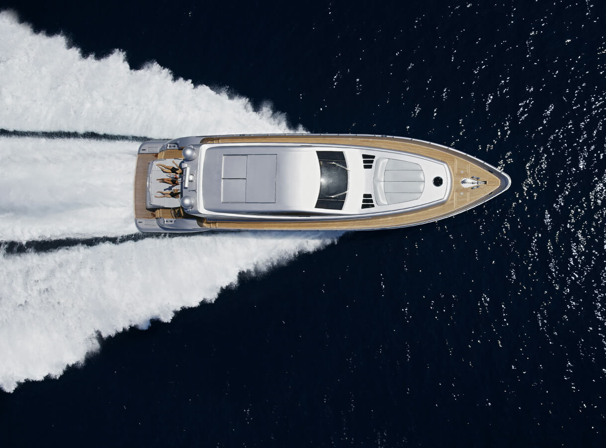
Unfortunately, this boat is not available for sale. It will be removed from the website soon.

Yachts with similar parameters:

Find a yacht

Azimut Grande 35 - AZIMUT / BENETTI

Azimut Grande 35 114' 10" AZIMUT / BENETTI 2018 PRICE ON APPLICATION

Specifications

Accomodations:
5 staterooms
Length:
114' 10" (35.00 m)
Beam:
24' 8" (7.50 m)
Draft:
6' 4" (1.91 m)
Year Built:
2018
Builder:
AZIMUT / BENETTI
Category:
Motor Yacht
Cruise Speed:
12 Kts. (14 MPH)
Max Speed:
26 Kts. (30 MPH)
Location:
Italy - West CoastItaly
Buy a yacht buy another yacht from our catalog
  • All Specifications
  • Detailed Information

Basic Information

Builder:
AZIMUT / BENETTI
Category:
Motor Yacht
Sub Category:
Flybridge
Model Year:
2017
Year Built:
2018
Country:
Italy
Fly Bridge:
Yes

Dimensions

LOA:
114' 10" (35.00m)
Beam:
24' 8" (7.50m)
Min Draft:
6' 2" (1.86m)
Max Draft:
6' 4" (1.91m)

Speed, Capacities and Weight

Cruise Speed:
12 Kts. (14 MPH)
Cruise Speed Range:
1500
Max Speed:
26 Kts. (30 MPH)
Max Speed Range:
500 Kts.
Gross Tonnage:
269 Pounds
Water Capacity:
3000 Gallons
Holding Tank:
2500 Gallons
Fuel Capacity:
18000000 Gallons

Accommodations

Sleeps:
10
Total Heads:
7
Crew Sleeps:
6
Crew Heads:
4

Hull and Deck Information

Hull Material:
GRP
Deck Material:
Teak
Hull Configuration:
Planing
Hull Color:
White Brilliant
Hull Finish:
Fiberglass
Hull Designer:
Azimut
Exterior Designer:
Azimut
Interior Designer:
Azimut

Engine Information

Manufacturer:
MTU
Model:
16V 2000 M96
Engine Type:
Inboard
Fuel Type:
Diesel

Description

The Italian yard adds that the Azimut Grande 35M (Hull n°14) features two superyacht beach clubs, one in the stern and one in the trapezoidal bow, which measures 30 metres square, excluding the walkways. This space has been put to good use with a hydro massage spa pool flanked by sofas and sunloungers. This entire area can be hydraulically raised to provide access to the winches and fender racks below. A side-loading tender garage provides storage for a tender and Jet Ski, leaving the transom free for accessing the water. In a first for this segment of the market, the upper deck will be available with a 30 square metre raised observation deck. 
Accommodation is for a total of ten guests, with four more guest cabins below decks, arranged as two doubles and two twins. A spiral superyacht staircase with backlit oynx steps connects all three decks on the Azimut Grande 35M. Meanwhile, the crew quarters is situated in the bow, with room for up to six crewmembers.
This Azimut will be sold with 2 years warantee on the engines and 1 year on the Yacht. 

Hull Structure

HULL AND DECK MATERIALS:

Hull and deck will be built in glass-fiber reinforced plastic (GRP).
The Yacht will be constructed in a combination of foam (closed-cell) core sandwich and single skin fiberglass construction utilising mat, unidirectional, and biaxial E-glass.
For the lamination of structural parts, hull, deck and reinforcements, a polyester isophtalic resin will be used.
The prevention of hull GRP osmosis will be guaranteed using a isoneopentylic gelcoat, in order to create a suitable barrier to sea water.
A further barrier to hydrolysis of the GRP laminate will be obtained using a vynilester resin for the execution of the skincoat (first lamination layers after the gelcoat).
Antifouling paint will be applied to the underwater hull as per Manufacturer recommendations.
The mechanical and chemical properties of the laminates will be verified by material tests in accordance with the Classification Society requirements.

HULL AND DECK CONSTRUCTION:

The structural design and assessment will be according to the most recent experience in design and construction of GRP for this type of Yacht. The hull structure shall be framed with structural bulkheads,
longitudinal and transversal stiffeners. The hull bottom will be built in single skin-type.
The hull side and main deck will be built, mainly, in GRP sandwichtype with PVC foam core. GRP tanks for fuel oil, sewage/greywater, fresh water will be integrated into the hull structure. Each structural tank will have at least one GRP manhole. Tank internal surfaces will be treated in order to avoid that the liquid stowed in the tank will penetrate the GRP material. All penetrations of piping and electric cables through watertight bulkheads will be watertight. Structural bulkheads will be built in sandwich-type GRP, consisting of a PVC foam, and composite marine wood panels.
The Yacht will be divided in four watertight compartments by watertight bulkheads. The watertight collision bulkhead will be positioned as standard configuration in accordance with the Classification Society requirements for Pleasure Yachts.
The Yacht will be equipped with a watertight transom door; the transom door will open turning down, creating a large bathing
platform integrated with the beach area, as per General Arrangement. A garage watertight compartment will be provided on lower deck starboard side, between the engine room and the beach area, for the positioning of one tender (Owner’s supply) and one PWC (Owner’s supply). A side watertight door will be provided, in order to allow launching and hauling of the marine vehicles stored in the garage. Two chain lockers will be provided forward the watertight collision bulkhead.
A GRP bow thruster tunnel will be installed and connected to the hull by means of GRP layers. GRP sea chests integrated in the hull bottom will be installed for main engines, generators and auxiliary services sea water supply. A structural keel will be built, in order to increase course keeping ability of the yacht. GRP bulwark will be built, as indicated on the General Arrangement,
and will be integrated into the hull sides. The bulwark will be equipped with freeing ports, in compliance with the Classification
Society Rules. Stainless steel profiles will be fitted on the “wave piercer” bow as protection from anchors’ chains.
Main engines will have main exhausts located below the waterline in GRP boxes integrated in the hull bottom, and will have the by pass exhausts located above the waterline. Exhaust scoops will be designed, in order to keep back-pressure
below the limit allowed by the engines Manufacturer. Diesel generators exhausts will be provided, with sea water discharge
placed under waterline and gas exhaust placed above waterline.

Navigation, communication and signalling equipment

NAV/COMM/SIGN EQUIPMENT:

The following controls will be provided in wheelhouse:
· steering actuator wheel,
· bow thruster control lever and running indicator,
· main engines throttles,
· MMEE key, start/stop buttons and alarm signal,
· emergency stop for main engines,
· stabilizer fins control panel,
· monitoring system.
The following controls will be provided on flybridge:
· steering actuator wheel,
· bow thruster control lever and running indicator,
· main engines throttles,
· MMEE key, start/stop buttons and alarm signal,
· emergency stop for main engines.

NAVIGATION SYSTEM:
Hull:
. 1 transducer Furuno B744VL
. Wheelhouse:
. 1 monitor Furuno 15” MU-150HD
. 1 multifunction display Furuno RD-33
. 1 autopilot Furuno Navpilot 700
. 1 rudder angle Furuno FI-506
. 1 VHF Furuno FM-4721
. 1 compass White Star B6W3/3-100

Flybridge:
. 1 multifunction display Furuno MFD12,
. 1 multifunction display Furuno RD-33,
. 1 autopilot Furuno Nav 711,
. 1 rudder angle indicator Furuno FI-506,
. 1 VHF repeater,
. 1 compass Zenith BZ1/3-143.

Roll bar:
. 1 radar antenna Furuno 4ft 6kW,
. 1 NAVnet 3D BB
. 1 VHF antenna BA 197,
. 1 GPS antenna Furuno GP-330B,
. 1 weather station Airmair WX 150.

Emergency station:
. 1 rudder angle indicator Furuno FI-506.

INTERCOM SYSTEM
One emergency internal communication system will be fitted in:
· wheelhouse,
· engine room,
· emergency steering location.
· aft cockpit
· fore mooring station

PHONE SYSTEM:
A PABX system for 9 phones (units available as option) will be
provided. Sockets are placed in the following areas:
· wheelhouse,
· salon,
· galley,
· master cabin,
· VIP cabins,
· guest cabins,
· crew mess.


Entertainment equipment

CREW MESS:
. 1 TV 22’’ Samsung LED UE22H5000,
. 1 Mini Hi-fi player Yamaha MCR-750,
. 2 loudspeakers Promar 6” PMS6.

TWIN GUEST CABINS:
Items to be considered for two cabins.
. 1 TV 22’’ Samsung LED UE22H5000,
. 1 Blue Ray player Sony BDPS590,
. 1 amplifier Denon AVR-X1100,
. 1 pair of loudspeakers B&W CCM362 (Square).

VIP CABINS:
Items to be considered for two cabins.
. 1 TV 22’’ Samsung LED UE22H5000,
. 1 Blue Ray player Sony BDPS590,
. 1 amplifier Denon AVR-X1100,
. 1 pair of loudspeakers B&W CCM362,
. 1 Apple TV,

CREW CABINS:
Items to be considered for three cabins.
. 1 Car stereo Sony
. 2 loudspeakers Promar 6” PMS6.

OWNER’S CABIN:
. 1 TV 40’’ full HD Samsung LED UE40JU7000,
. 1 Blue Ray player Sony BDPS590,
. 1 amplifier Bose V35,
. 1 Apple TV.

MAIN SALOON:

. 1 TV 55’’ full HD Samsung LED UE55JU7000,
. 1 Blue Ray player Sony BDPS590,
. 1 amplifier Bose V35,
. 1 Apple TV.

EXTERNAL MAIN DECK – AFT COCKPIT:
. 4 loudspeakers Promar 8” PMR8
. 1 amplifier Bose SA-3

CAPTAIN CABIN:
. 1 Mini Hi-fi Yamaha CRX-N560 CD
. 2 loudspeakers Promar 6” PMS6.

FLYBRIDGE:
. 4 loudspeakers Promar 8” PMR8
. 1 amplifier Bose SA-3

EXTERNAL MAIN DECK BOW LIVING AREA:
. 2 loudspeakers Promar 8” PMR8
. 1 amplifier Bose SA-2

Stabilizers

Nr. 2 electrical stabilizer fins (CMC Stabilis Electra SE80-7-4-160) working underway and at anchor will be installed. The fins will be
provided with an electrical motor having 7 kW input nominal power supplied by generators. Fin area will be 1.6 m2. Control panel will be installed in the wheelhouse. Installation will be done strictly according to Manufacturer instruction.
Voltage will be 400 Vac, 3 phases, 50Hz, duty cycle S1.

Engines room

ENGINES & GENERATORS:

Two turbo charged after cooled four stroke diesel engines suitable for marine propulsion will be installed on the dedicated foundations in the engine room:
MTU16V2000M96, of 1790 kW (2400 BHP) @ 2450 rpm each, with Blue Vision NG Basic electronics.
Exhaust emissions of these engines are in compliance with EPA TIER III and IMO TIER II regulations. 
The generating system will consist of two diesel generators with the
following characteristics:
· Manufacturer: Kohler
· Models: 55EFOZDJ
· Rated outputs: 53 kW
· Rated voltage and frequency: 400V AC / 50 Hz
· Number of phases: 3
· RPM: 1500
· Insulation class: H
· Tension regulation: ± 0.5 %
· Frequency regulation: 0.5 %
· Starting system: 12 V DC


MAIN VOLTAGE SYSTEM:

Electrical equipment, wiring, fixtures, boards, switches, etc. will be designed, located, installed and tested according to the Classification Society rules, regulations and requirements.
Electrical equipment will be selected and located to ensure adequate protection against damages from water, oil, humidity, vibration and will be arranged in such a way to facilitate access for maintenance.
Distribution The electrical distribution will be as hereafter described:
Main machinery 400V AC / 50Hz / 3 phases Lighting and household appliances, stereo, TV sets, and other low power users 230V AC / 24V AC, single phase Emergency lighting system 24V DC battery system, Service equipment 24V DC battery system
Radio equipment 24V DC battery system The AC power will be supplied by two diesel generators or by a shore
power system.

STARTER DEVICES & PANELS:

Where possible, starters and protections of equipment located in the engine room will be centralised in the main switchboard.
Start-stop push buttons can be positioned on the main switchboard or locally near the users according to the engine room available space.
Cables with stranded wires suitable for marine use will be used. All supply cables for electronic equipment shall be of the shielded type. Cables will be of the multiple conductors type for all AC circuits and meeting Classification Society requirements. All cables connected to terminal blocks will have 'ferrule end connectors' or other approved means of connection as per the Classification Society requirements. All the wires and terminal strips will be marked with identification code in the switchboard, in junction boxes and at the termination of the wire. Shielded cables will be used for low power equipment liable to be affected by strong magnetic or electrostatic fields. All connection boxes (also in the accommodations) will be made accessible. Penetration of watertight bulkheads will be done with approved sealing systems.

ENGINES BATTERIES:
Two groups of 24V DC batteries for main engines starting. Capacity according to engine Manufacturer requirements. Each group will be dedicated to one main engine. Two groups of 12V DC batteries for diesel generators starting.
Capacity according to generators Manufacturer requirements. Each group will be dedicated to one diesel generator.
Two groups of 24 V DC batteries for main engines electronics. Each group will be dedicated to one main engine.
One group of batteries for motorpump starter.

Bilge and fire system

FIRE PUMP:
. 1 electric self priming pump will be installed in the engine room for sea water fire extinguishing system. The pump will be connected with the motorpump.

BILGE PUMPS:

. 1 electric self priming pump will be installed in the engine room for main bilge system. The pump will be connected with the
motorpump.
. 1 dedicated electric pump will be installed for the garage bilge system.

MOTORPUMP:
. 1 motorpump will be installed for bilge and fire systems.

BILGE AND FIRE PIPING:

Each watertight compartment will have a separate bilge suction, with electric valve, connected through a bilge manifold to the electric pump. Bilge lines will be in stainless steel AISI 316 on suction side and in CuNi 90-10 on delivery side.
Vacuum and pressure gauge sets will be arranged in a support as close as possible to the main bilge pump, fire pump and motorpump. The garage will be protected by a water jet nozzles’ system connected to the fire main by a manually operated valve.
Fire hydrant valves, with fire hoses and nozzles, will be fitted in the following positions:
. 2 on main deck,
. 1 on flybridge.
The hawse pipes will be connected to the fire manifold for sea water chain washing. Fire lines will be in CuNi 90-10 of the pressfitting type.

ENGINE ROOM FIRE EXTINGUISHING SYSTEM:
A FM 200 fixed fire extinguishing system will be installed for engine room, with adequate nozzles and a release handle fitted on the emergency control panel situated near the acces to the engine room/garage area.
image description