- Builder:
- Mondo Marine
- Category:
- Motor Yacht
- Sub Category:
- Tri-Deck
- Model Year:
- 2016
- Year Built:
- 2016
- Country:
- Italy
sales and service of boats, ships since 1959.
№1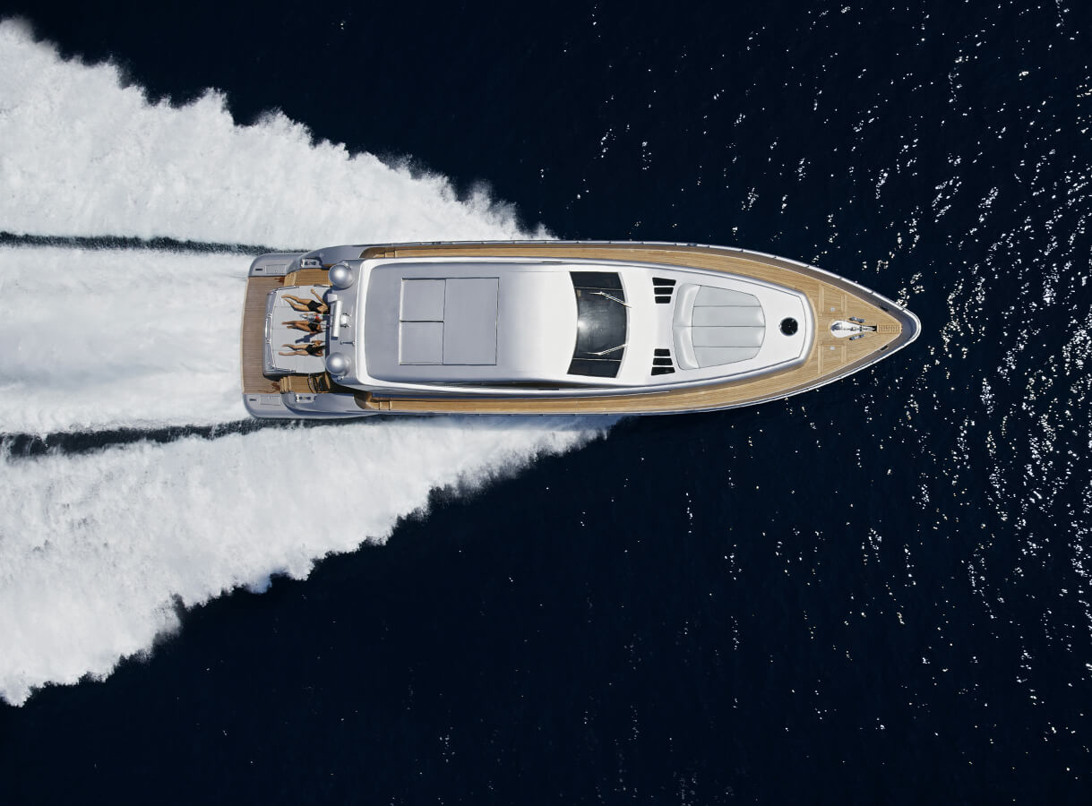
Unfortunately, this boat is not available for sale. It will be removed from the website soon.
Mondo Marine - available for sale:
Yachts with similar parameters:


The vessel will be built in accordance to the Lloyd’s Register of Shipping regulations. Class notation will be 100 A1 SSC Yacht Mono G6 LMC. Upon delivery of the vessel, a Provisional Certificate of Class will be issued. The Cayman Islands Shipping Registry (Flag) shall conduct surveys and plan appraisals for compliance with Large Commercial Yacht Code 2 (LY2).
The Class, on behalf of the Flag, will issue the following certificates:
• International Load Line 1966
• Marpol Annex I (Oil)
• Marpol Annex IV (Sewage)
• Marpol Annex VI (Air pollution)
• Safety Construction
• Safety Equipment
• Cargo Ship Safety Radio
• International Tonnage 1969
HULL CONSTRUCTION
Hull and decks are entirely built under Classification Society control and survey.
The hull is divided in 6 watertight compartments designed according to Classification Society rules. The hull will have a partial double bottom with integral tanks for fuel, lubricant oil, fresh water and wastewater. The bow thruster is fitted in a separate watertight compartment. The structure consists in transversal and longitudinal stiffeners, such to achieve maximum strength and minimum weight.
DOUBLE BOTTOM TANKS
The sides and swash plates of the double bottom tanks are continuations of the longitudinal girders and transverse frames and are executed in such a way that the contents will run freely to the deepest point. The tanks are fully accessible through manholes and lightening holes in the internal swash plates. The manholes as well as all tank fittings and connections shall be readily accessible at
all times. Tanks shall be fitted with ventilation pipes, connection for supply/return lines, sounding system and alarms (Grey waters, diesel oil overflow, sludge, bilge, black waters). The day tanks will have visual sounding system. All welds in water, grey and black tanks to be 100% on both sides of all stiffeners, baffles, longitudinals, t-bars etc.
ENGINE FOUNDATIONS
The main engines girders are continued in both the fore and aft direction, thus becoming an integral part of the girder system. The structural arrangements are laid out in a manner allowing good access for tools and hands to perform the necessary installation, maintenance and cleaning work.
ENGINE ROOM FLAT & FLOORING
Steel angle bar support for steel or aluminium flooring will be provided in Engine Room for engineer walking. Angle bars serving as a rim around floor perimeter.
The floor is divided in easy removable sections to access the bilges and the equipments underneath.
AFT COMPARTMENT
The astern compartment accommodates the Owner’s tender and technical spaces for the power packs of the steering system, for the crane, for the hydraulic bathing platform etc, and a bathroom as described in the GA. The garage will be closed by an upward opening hinged door as described in GA.
BATHING PLATFORM AND TRANSOM DOOR
The transom door will be hydraulically operated and upward opening. When in the closed position, hydraulic securing pins will lock the door in position. The bathing platform is to be teak decked with margin boards as per the Exterior Designer’s directions.
SHAFT BRACKETS
Shaft brackets are provided of "L" type. The shape and thickness keep in consideration the number of propeller blades and propeller revolutions to avoid structural resonance. Shaft brackets are constructed of steel and welded to the hull and skeg construction. Shaft brackets scantling will be in accordance with Class rules.
SCUPPER BOXES
Scupper boxes will be provided in number and position to assure complete water drainage and discharge from all weather decks. On the scupper box there will be a removable stainless steel screen to prevent debris from
SUPER STRUCTURE CONSTRUCTION
Superstructuers of the 1st tier aft of the wide body zone, and the upper zones, are made of aluminium alloys (AA). The structure is of longitudinal type, with longitudinal stiffeners spaced abt 300 mm for decks and 350 mm for the sides. Transversal frames are spaced identically to the hull. The thickness of the decks and superstructure side is 5 mm or 4 mm, with local thickness reinforcement in correspondence of deck openings (stairs etc). The internal division bulkheads have a thickness of 5 mm and vertical stiffeners spaced abt 300 mm. All the welding of AA superstructure will be performed using MIG process, according to the Classification Society requirements. The connection between the superstructure and the main deck will be obtained by a bimetallic joint of a type approved by the Classification Society. The houseside/deck plate joining are all to be double butt welded. The same bi-metallic
joint is used to connect the steel to aluminium for all stiffeners, framing, deck beams, t-bars, webs, girders etc. Opening in superstructure stiffeners for pipe, duct and cable-ways will be properly reinforced by collars according to the Classification Society Rules. The collars shall be lined to prevent wear or damage to pipe & ducting insulation and wire & cable coverings.
CASINGS
Engine Room ventilation casings will be provided, properly reinforced and insulated to achieve the minimum noise transmission to the adjacent accommodations.
STAIRCASES
All staircases below the main deck shall be fully constructed of the same steel as the hull, for the purpose of safety and noise reduction. The staircases above the main deck will be of aluminium and welded integrally with the superstructure.
External steps will be teak covered. Deck openings will be protected at sides with stainless steel hand railing on stainless steel stanchions, diameter of railing and stanchions 40 mm, intermediate rails 25 mm. Position and size as shown on General Arrangement.
OUTFITTING RECESSES
Into the superstructure suitable recessed boxes will be built, for: fire hydrants, life-rings with light-buoy and rope, deck washing-down plugs.
MASTS
Aluminium alloy main mast will be provided as shown on the External Profile.
The main mast design will include platforms and other adequate supports for navigation and communication antennas and radomes, masthead wind unit, navigation, anchor and signaling lights etc. The definitive drawing including the positioning of all the communication, navigation and TV antennas and radomes will be approved by the electronics supplier and consultants. Mast and platforms to be fitted with the required number of flush access hatches for the servicing of equipment or the eventual passage of extra cables.
GENERAL
The Yacht is conceived as an extremely soft riding, seaworthy vessel. All machinery is selected and installed accordingly with elastic mounting of all rotating machinery where appropriate. Special care is taken in ordere to make the systems operate quietly, to achieve low noise levels. The layout and execution of the machinery, accessories and installations will be for shipboard use.
MAIN ENGINES
Two turbo charged after cooled four stroke diesel engines to be installed on flexible mountings.
Engine Type: CATERPILLAR 3516B-HD DITA SCAC (series II)
Power: C rating (max cont rating) 2000 kW (2682 HP) at 1600 rpm
Each engine is elastic mounted on RD214 mounts (45 shore) in order to absorb vibrations. The main engines shall have an electronic controlled automatic synchronisation system. The design and installation of all piping relative to the main engines shall be in accordance to the engines manufacturer installation specifications. The engines will be equipped with all necessary manufacturer's supplied accessories, such as heat exchangers, sea-water pumps, duplex fuel filters, fuel injection pump. The jacket water piping system shall be fitted with a sediment filter with bypass to allow filter replacement whilst in operation.
Electric starting system provided for main engines as per manufacturer recommendations and Class rules. Electronic engine controls, according to engine manufacturer. Local control in Engine Room, main station in wheelhouse, manoeuvring stations at the side wings (port and starboard).
RUDDER AND STEERING GEAR
Two balanced spade rudders are fitted. Rudder fin is made of steel, stock material is AISI 316L. Zinc anodes to be provided. Rudder stock diameter is in accordance to class requirements. Bearing material is Thordon XL or equivalent. Steering gear system maker OPEM Sistemi is fitted. Hydraulic power pack is provided with two electric pumps (one in stby) 3 kW each. Two hydraulic actuators synchronized by
means of a steel rod transmit necessary torque to rudder stocks through tillers.
Steering gear tillers are provided with mechanical stoppers limiting the rudder angle to 35° (stb and prt). Rudder angle indicators are provided in wheelhouse, wing stations and emergency steering position. The power pack is fitted in the aft technical spaces and supplies pressurised oil to the system; it consists in two electric pumps and an oil tank equipped with filters, solenoid valves, relief valve, oil pressure and level gauges and a tank low level alarm. The power pack tank is divided into two sections, each section supplying a separate pump. There are shut off valves to isolate either pump for maintenance. All valves are installed on a well organised, neatly piped, manifold. Each valve shall be accurately marked.
The piping from power pack to cylinders shall be suitably supported and mounted in a straight and uniform manner. All flexible hose lengths shall be double braided, rubber jacketed stainless steel Aeroquip or similar. The hoses shall be laid & mounted in a straight & uniform manner. Emergency steering system consists in a hydraulic manual pump fitted in the aft garage. Nearby emergency steering position a gyro repeater, intercom and magnetophone shall be
installed (see relevant chapters). Piping and hose to the emergency steering system will be independent of the normal
working system, isolated with three way valves directly connected to each steering actuator
BOW THRUSTER
Bow thruster ABT TRAC maker, electric driven by abt. 110 kW motor, two propellers, tunnel diameter abt 800mm. The bow thruster will be fed directly by the main electrical switchboard. Bow thruster controls will allow operating thrust direction and revolutions from wheelhouse and wing stations. Hull at bow thruster tunnel insertion shall be properly faired to minimize drag and proper
guard grid shall protect thruster’s propellers. The bow thruster compartment is a watertight space with a watertight access hatch from lower deck crew area. It will be fitted with ventilation. The ventilation ducting shall have a shut off valve on both the supply and return easily accessible where it exits the compartment.
All electrical cables passing through the compartment shall pass through suitable watertight fittings. The compartment shall be fitted with lighting, bilge alarm and suction. There shall be a removable access ladder inside the compartment to facilitate access.
STABILIZERS
A pair of non-retractable fin stabilizers is installed, maker Vosper-Naiad, with anchor and under-way stabilizing capability. Fins dimension is 3.49 m2, actuator model 620. Two electrically driven indipendent hydraulic pumps will be fitted on a power pack located in a dedicated compartment of the under-lower deck forward of the Engine Room. Each pump can operate the system at full performance under way, while both pumps work sequentially when stabilizing at anchor. Hydraulic power pack is cooled by two cooling pumps, one in service the other standby. Stabilizers actuators are fitted in watertight compartments accessible from under-lower deck tunnel. The watertight compartment will have watertight hatch for access and inspection. The compartment shall be fitted with lighting, bilge suction and level alarm. All electrical wiring into the compartment shall pass through suitable fittings.
BILGE SYSTEM
Watertight compartments (except forward of collision bkd) have dedicated bilge suction and lines leading to the engine room central manifold and connected to it through electrically actuated valves. The manifold is served by an electric self-priming pump (G&R ACM 651BT or equivalent) in parallel with the main fire pump. Each bilge well is fitted with dedicated bilge alarm.
Aft lazarette is provided with 4 indipendent bilge suctions leading to an intermediate manifold connected to the engine room main manifold. In addition independent bilge system is provided by mean of dedicated bilge pump.
Bosun store and chain locker bilge suctions are connected to dedicated electric pump (G&R CP40S or equivalent) and to emergency manual pump.
One emergency bilge (and fire) electric self-priming pump is fitted outside of Engine Room in the sprinkler compartment G&R ACM 651BT or equivalent). This pump will be supplied by the Emergency Diesel Generator through the Emergency Switchboard. Pumps will be fitted with vacuum/pressure gauges as per system drawing. Emergency bilge suction for Engine Room through main engines is provided. A bilge water separator is also fitted in engine room, in compliance with applicable MARPOL regulations, type DVZ-150 FSU. The unit will be completed with bilge oil content alarm monitor. The separator will take oily water from bilge tank and after separation, clean water is discharged over board and residuals are sent to the sludge tank. Sludge tank can be discharged by dedicated pump (G&R CP32 or equivalent) through international shore connection as per applicable MARPOL regulations. All bilge suctions will be fitted with a foot valve and strainer. Bilge system piping shall be CuNi 90/10, valves material bronze.
FIRE SYSTEM
The system is driven by a main fire pump (G&R ACM 651BT or equivalent) in parallel with the main bilge pump. The main pump is installed in engine room and is connected to the fire main manifold; proper valve as per regulation is provided in order to isolate engine room fire main manifold section. The emergency fire (and bilge) pump has dedicated sea chest and it is supplied by the
Emergency Diesel Generator through emergency switchboard. Pumps will be fitted with vacuum/pressure gauges as per system drawing. International flanged connection is to be provided. Fire main manifold will suplly water to fire hydrants onboard as per regulation; the following hydrants will be installed:
BALLAST SYSTEM
The ballast system serves the fore peak tank (bulb). Suction from tank is made by the bosun store bilge pumps (see.IV.1), while delivery is connected to the fire system with appropriate isolation valve. Ballast pipes in CuNi 90/10. Valves in bronze or stainless steel. Fore peak tank can also be used as fresh water reserve tank for the pool. Appropriate system for pool filling and emptying is provided.
FUEL FILLING, TRANSFER, SERVICE AND OVERFLOW SYSTEM
The transfer and filling system includes the low-pressure piping required for filling the tanks and for the transfer of fuel from one storage tank to the day service tanks for immediate use or another storage tank when necessary for trimming the ship. Two hidden filling stations (on the main deck port and starboard) with DN 65 piping will be built with drains and hard connection quick release fittings for quicker fuelling. Gravity filling pipes lead to the transfer main valve box manifold.
Frome the main valve box manifold it is possible to deliver to or to suct from each fuel tank by mean of the transfer pumps. Two electrical pumps (G&R ACM 401BT) and one manual pump are provided. The diesel oil carried in the storage tanks can also be transferred through a centrifugal purifier to the day service tanks or to another storage tank or returned to the same tank (Make: Alpha Laval). From the day service tank crossover pipe, fuel is deliverd to the engines and generators through appropriate filters. Diesel tender fuelling system supplied by the day-tanks will be fitted in the tender garage. A line for filling the emergency diesel generator dedicated tank is provided. Each diesel oil storage tank is connected to the overflow pipe which leads to the overflow tank. Service tanks have dedicated overflow pipes to the overflow tank. From the overflow tank it is possible then to suct fuel by mean of the transfer pumps. Fuel system piping is carbon steel ASTM 106 grade B, valves material steel.
MAIN ENGINES EXHAUST SYSTEM
Main engines exhaust gas is discharged overboard through appropriate silencers.
Connection between engine and silencer and between silencer and following exhaust line is done by mean of flanged compensators in order to absorb thermal elongations of the line. Before to be discharged overboard, exhaust gas is water cooled into an appropriate stainless steel cooling chamber. Then it flows below the waterline into a submersed exhaust chamber and into a bypass exhaust slightly above the waterline. Since submersed exhaust will work mostly at high speeds the bypass exhaust is provided for the low rpm cruising speeds.
An electrically actuated valve is installed for the purpose of closing the bypass exhaust. As per Class requirement a manual valve is installed on the main exhaust underwater branch. The support of the main engine exhaust system shall be elastic. Connection of cooling water pipes is done with flexible hoses. All hot exhaust gas piping shall be appropriately insulated. The system will be designed in order to mantain back-pressures within the limit noted by the main engine manufacturer. Dry exhaust piping material is carbon steel.
DIESEL GENERATORS EXHAUST SYSTEM
The generators exhaust lines are fitted with silencers, watermisting devices (raisers) in stainless steel, water lifts and water separator boxes, then exhaust gas and cooling water are separately discharged overboard
FRESH WATER SYSTEM
Fresh water storage tanks can be filled through the filling station on main deck aft. On the filling station line a chlorinization device is installed. A watermaker with dedicated seachest is also installed (Type IDROMAR MC8 duplex, 15000 lt/day) with delivery line to fresh water storage tanks. Two pumps with electronic control of pressure head and flow, 380 V, 50 Hz (G&R ACM402BT or equivalent), deliver cold water to the system, through ultra-violet filter. Also a direct pressure plug connection from ashore is provided. The hot water system is based on a recirculating principle (two blowers WILO Z30 TOP are provided). Hot water cecirculating ring pipe rise till below upper deck in proximity of the upper deck users. 4 Boilers 250 litres (6+6 kW) each are provided. Cold and hot water lines will be executed outside of the engine room with polypropylene or C-PVC or equivalent. Piping in engine room will be in stainless steel. A cold water washdown system, connected with the main fresh water system, will be supplied.
The following plug will be provided:
• Three on main deck (aft portside, starboard nearby side ladder, forward on forecastle)
• Two on upper deck (forward, aft)
• One on sun deck
• One in tender garage
• One in Engine Room
Additionally hot and cold water facility is provided for the swimming platform.
SEWAGE AND SANITARY SYSTEM
A Jets or similar vacuum toilet system will be fitted. Toilets will discharge directly into the vacuum main manifold, while grey waters will be collected before by jets collecting tanks. The vacuum system will be maintained by two independent vacuum pumps (type Vacuumarator Jets), delivering to the black water tank.
Also grey water tank is provided for collecting waste water from washing machines and galley discharges with dedicated pump for discharge. Galley will discharge through macerator and grease trap. A sewage treatment system by Hamann (capacity 24 m3/day) is provided. Shore discharge is provided by same Jets pumps through international flange. Piping will be in Geberit or equivalent in the accommodation areas. Stainless steel will be used in the engine room.
FIXED FIRE EXTINGUISHING SYSTEM
A fixed fire extinguishing system is installed in order to fulfil regulation in matter of protection of both accomodation spaces and Engine Room. System is of High-Pressure Water-Fog sprinkler type (maker Ultrafog or equivalent). Accomodation spaces protection system is divided in four sections (typical) and includes a suitable nuber of glass bulb activated nozzles (system starts automatically if bulb temperature raises above 57°C). Also galley hood is protected by the same system
Total flooding for protection of machinery space is provided by suitable number of open head nozzles and bilge nozzles. Bilge nozzles will blow a mixture of foam and water. Also aft lazarette is protected with open nozzles on a separate dedicated section. Each section can be manually activated by means of push buttons in fire station, wheelhouse and another suitable position (i.e. crew mess).
GENERAL
The vessel electrical system will be designed according to the selected Classification Society Rules for Charter Yachts, and it shall also comply with the following standards or equivalent national ones, even if not limited to them:
IEC Publications 60092 – Electrical Installations on Ships
IEC Publication 363 – Short Circuit Currents Evaluation
IEC Publications 439 – Low Voltage Switch Gear and Control Gear Assemblies
IEE Regulations for the Electrical and Electronic Equipment of Ships (sixth editions with
related amendments )
In particular all the above mentioned Rules apply to the components of electrical
installations for services essential to the propulsion, steering and safety of the yacht and services for habitability. The design, construction and installation of all electrical equipment will be suitable for marine service conditions. The electrical power distribution on board will be 400 V, threee phases, 50 Hz, distribuited
by a 4 wires system with insulated neutral, to allow the single phase 230 V, 50 Hz,
equipments to work using one phase and the neutral. 24Vdc users will be fed by suitable 230V/24V converters or dedicated service battery banks. A main switchboard, designed with a split bus system with bus-tie automatic circuit
breaker, and which is fed by the main generators and/or by the shore supply (below described in details), will supply all the main services, via individual automatic circuit breakers, while all the minor users will be fed by suitable sub-distribution switchboards and panels, also equipped with automatic circuit breakers, and connected to the main switchgear. The yacht power generation and distribution will be managed by a proper Power Management system (PMS)
All automatic circuit breakers protecting the single electrical services, sub distribution panels and final users will be chosen in compliance with relevant Class requirements and following short-circuit calculations. All electrical devices, and their connection/junction boxes, will be installed in easily reachable positions for maintenance purpose and duly protected against any electrical, electrostatic and mechanical possible damages, as well as against contact with water, oil, fuel
or heat sources. All the electrical devices exposed to weather will be watertight type, with a protection degree at least IP65, or higher according to the place of installation. All cable penetrations through bulkheads or decks will comply at least with their watertighteness and/or fire division requirements. All the metal enclosures containing electrical equipments will be duly connected to ground. All equipment cover plates will have high quality labelling that clearly identifies the purpose of the corresponding device.
ELECTRICAL POWER GENERATION
The electrical system will be fed by three main diesel generators type
CAT C9 DITA, 150 kW (188 kVA) 400 V 50 Hz, capable of running continuously in parallel operation. The main generators will feed the two 400V, 50HZ,3ph+neutral bus-bars of the main switchgear. The parallel operation of the generators can be performed both manually and automatically, with automatic active and reactive load sharing. A shore power converter, with rated power 100kW (0,8 p.f.) at 400V,50HZ, 3phase + neutral will be provided. The shore power converter will consist of one or more modules, capable to be fed at a voltage in the range from 170V to 520Vac, 40/70HZ, 3phase, and with the above said output, acting in this way also as galvanic insulator from the ashore electrical system; the output shore supply cables will feed one of the two bus-bars sections of the main switchgear, via an automatic circuit breaker, with seamless operation in respect of the main
In case of failure of the PMS, or by operator choice, a manual management of the three generators start/stop, connection to the net and parallel operation will be anyway possible. A 24Vdc system will also be installed. The system will be supplied by suitable 400Vac/24Vdc converters or by Gel type battery banks, kept in charge by steady state battery chargers with automatic voltage and current controls. For the 12Vdc users, when necessary, individual 24Vdc/12Vdc converters of proper power will be installed.
EMERGENCY SOURCE OF POWER
The emergency source of power is supplied by a 68KW (abt) Emergency Diesel Generator (E/G). The emergency generator will start automatically (within the time limits set by the applicable Rules) as a black-out occurs and will automatically connect to the emergency switchgear, which in normal operation is connected to the main one. The emergency switchgear services will be those clearly stated by the Rules, and anyway will be at least the following:
Emergency bilge/fire pump Water mist fire fighting system Emergency/service batteries 24Vdc distribution system power converter Engine room fire fighting system During the transition between black-out and E/G starting, transitional power for emergency lighting will be supplied by dedicated battery packs.
YACHT MONITORING SYSTEM
An YMS system, consisting of a dedicated automation processor, and a set of 3 interfaces, are installed on the vessel. The purpose of the YMS is that of monitoring the entire vessel, in a simple and streamlined way, giving to the crew in charge all the essential information for an efficient and safe ship management.
All the equipment used for the YMS system will be manufactured by first class Makers. The visual control of the different functions will be done through 3 dedicated 15” LCD displays, from where all the operations allowed by the software can be performed. Control screen locations will be as follows:
• Wheelhouse
• Engine control room
• Crew mess (or alternative location)
The monitors will give both acoustic and luminous warning of all the individual alarm that could occur (according to the approved functions list), but only the acoustic alarm can be stopped, while the flashing signalisations of critical alarms can only be acknowledged and converted to steady light. The turning off of the alarm requires the reset of the fault condition by the crew in charge. The list of the standard functions integrated into the YMS system is the following:
Watretight and weathertight doors and hatches, monitorin and alarms,
Bilge alarms, Navigation lights, monitoring and alarms, Tanks, level monitoring and alarms, Generators, monitoring and alarms, Main Engines alarms Steering system fault Power Management System, monitoring of loads and control of power sources (diesel generators and shore power converter)
LIGHTING SYSTEM
GENERAL
The lighting system will be designed to give a high quality lighting level, as required by the class of the vessel. In principle four areas will be distinguished for number, type and features of the lighting system:
• Guest accommodation (VIP and guest cabins, salons, Owner’s cabin, lobbies,
stairs, dayheads, wheelhouse)
• Crew quarters (Captain and crew cabins, galley and pantries, crew lounge, laundry)
• Exteriors
• Machinery and technical spaces (E/R, garage, technical rooms, bosun store etc)
During the normal operation the power supply of the lighting system shall be done at 220Vac,50Hz, locally stepped down to 12/24Vdc where required. In all areas a suitable number of lights shall work in emergency conditions: the emergency lighting system shall be fed from the emergency switchgear, as previously described. The choice of the lighting fixtures, control switches, dimmers and sockets to be done according to the Interior Designer specification, and within, but not limited to, the specified allowances. Anyway the lighting fixtures will be selected in such a way that the internal wiring location temperatures do not exceed the temperature rating of the cable.
ELECTRONICS
GENERAL
The vessel shall be fitted with the following:
Navigation equipments,
• GMDSS communication antenna and equipments
• An automatic telephone system
• An interphone system
• A magnetic telephone system,
• A closed circuit TV system
• A service bell system
• A data network system.
The systems will be chosen, designed and installed in conformity to the following criteria:
• Compliance with applicable Class and/or Flag requirements
• Within the allowances set for each system (see following chapters)
• After approval of the system suppliers
• In compliance, where applicable, with relevant Interior Designer drawings
• In consultation and in agreement with Owner’s Representatives.
The layout of the wheelhouse will account for separation of the piloting and charting area from the radio communication area, for the maximum efficiency of the different operations when the yacht is underway. The wheelhouse arrangement will incorporate modular integrated consoles with the following advantages :
rational splitting of he various functions;
ergonomic operations;
collection of navigation and communication equipment in dedicated areas;
easy maintenance and better access to segregated or built-in functions; easy replacement or intervention on the power supply on the antennas interfaces, or on fuses and other protections.
The joinery work and decor design of the wheelhouse will incorporate the various
equipments and it will conform to ergonomic design criteria.The location, the accessibility of control panels and switchboards, and the visibility of displays, will be carefully evaluated. In general the following further criteria will be adopted:
Most equipment, and mainly those playing a major role in the ship’s reliability and safety, will have an emergency power supply and will be served by suitable UPS (Uninterrupted Powering Systems); The internal lighting will be designed to allow good visibility of the equipment and charting table, avoiding reflection on front windows at night; The antenna cables and wires will be laid on separate railings, in order to avoid ,or anyway limit, magnetic interferences; proper filters will be installed in case that interferences with the power distribution system will be found.
NAVIGATION EQUIPMENT
An allowance of Euros 180.000,00 is set aside, but not limited to, for navigation instrument supply and installation. The final equipment listing and installation is to be previously approved by the Owners Representative and chosen at a later date. The concept is that of getting a large integration of information to be addressed both to the screens of a Safe Navigator System and to the radars displays.
As reference the following equipment have been foreseen to be installed on board :
Radar n° 1, consisting of
Furuno XN-12AF antenna unit,
Furuno RPU-013 Processor unit
Furuno RCU-014 control unit
Furuno ARPA board
19” monitor unit,
Interfaces with NMEA distr., Speedlog, AIS, Gyrocompass, avigation PC (Transas)
Radar n° 2, consisting of:
Furuno XN-12AF antenna unit,
Furuno RPU-013 Processor unit
Furuno RCU-014 control unit
Furuno ARPA board
19” monitor unit,
Interfaces with NMEA distr., Speedlog, AIS, Gyrocompass, avigation PC (Transas)
Gyrocompass system, consisting of:
Simrad GC85 gyrocompass,
Simrad GC85 Control Unit,
1 Gyro repeater in wheelhouse
1 digital display in Emergency Steering Gear
Interfaces with NMEA distr., with autopilot and radars
Connection to UPS
Autopilot system, consisting of:
Robertson J50 processor Unit, interfaced with NMEA distr. gyrocompass and steering system
Robertson AP 50 Control Unit
Robertson RF35 Flux gate in wheelhouse
2 x Robertson FU50 follow-ups on the wing stations
GPS system n° 1, consisting of:
Furuno antenna unit
Furuno GP-150 display unit
Interafces with NMEA distr. systems
GPS system n° 2, consisting of:
Furuno antenna unit
Furuno GP-150 display unit
Interafces with NMEA distr. systems
Furuno MD-550 NMEA Buffer
Transas system, consisting of:
Navigation PC with Navichart 3000 ECS
Trackball and cordless keyboard
19” monitor unit
Transas Naviconning system, consisting of:
Naviagtion PC with naviconning 3000
Trackball,cordless keyboard and 19” monitor unit in wheelhouse
AIS system, consisting of:
Furuno GPS and VHF antenna
Furuno FA-150 display unit
Furuno FA-150 transponder unit
Echosounder system FE-700, co
nsisting of:
Furuno FE-701 control unit
Furuno FE-502 distribution box, with interfaces with NMEA distr.
Furuno 50/200 kHz transduces at hull
Speedlog system, consisting of:
Furuno DS800 control and display unit
Furuno DS 801 terminal board, with interfaces to radar system, gyro, NMEA distr., AIS
Ewather station, consisting of:
Furuno PB-150 weather station
Digital display RD 30 multidata
The navigation system shall be also provided of a VGA converter, with input from
navichart PC and output to AV equipments, to show the nav. data on the entertainment system.
COMMUNICATION EQUIPMENT
An allowance of Euros 100.000,00 is set aside, but not limited to, for communication instrument supply and installation; the final equipment listing and installation is to be previously approved by the Owners Representative and chosen at a later date. GMDSS rules shall be used as a guidance for the communication system installation. Spare coaxial cables and regular electrical cables shall be installed in order to allow a future easy
GMDSS system upgrade. Here below the equipment to be installed are listed:
VHF system n°1, consisting of:
1 Banten DC/MLL VHF antenna RX
1 Banten DC/MLL VHF antenna TX/RX
Furuno FM8800 control unit
VHF system n°2, consisting of:
1 Banten DC/MLL VHF antenna RX
1 Banten DC/MLL VHF antenna TX/RX
Furuno FM8800 control unit
VHF system n°3, consisting of:
1 Banten DC/MLL VHF antenna
Icom ICM421 control unit
SSB system, consisting of:
Banten AT7 antenna
Banten AT7 load antenna RTX, with furuno antenna tuner
Furuno FS 1570 T transceiver unit
Furuno FS1570T control unit
External loudspeaker
Navtex system, consisting of:
Furuno NX-7H antenna
Furuno NX-7001 receiver unit
Furuno NX-700 display unit
Inmarsat C n° 1 system, consisting of:
Furuno Felcom 15 antenna
Furuno Felcom 15 control unit
Furuno Felcom 15 printer unit
1 distress alarm unit
1 distress alert control unit
2 x SSAS IC-307 alert unit (one in Captain’s cabin)
Inmarsat C n° 1 system, consisting of:
Furuno Felcom 15 antenna
Furuno Felcom 15 control unit
Furuno Felcom 15 printer unit
1 distress alarm unit
1 distress alert control unit
Safety system consisting of
2 handheld VHF GMDSS radio
1 EPIRB
1 SART
The wingstations, the crew mess and the Captain’s cabin shall be fitted with digital data repeaters Further to the above mentioned equipments, and included in the above mentioned allowance, a VSAT Seatel 4006 antenna will be supplied and installed for satellite internet communications.
AUTOMATIC TELEPHONES SYSTEM (PABX)
A PANASONIC automatic telephone system will be installed on the vessel, covering both cabins and public spaces. The system will consist of the following:
PABX exchange, Panasonic KX-TDA30NE, with up to 52 internal extensions and
following features:
• Possibility to establish Incoming Call Distribution Groups
• Possibilty to forward your calls to a voice processing system and let calling parties
leave messages in your mailbox
• Support for optional portable stations
• Record of print out call information: date, time, extension etc...
1 digital telephone unit for each cabin and public space, (type KX-DT321SP for reference) An allowance of Euros 10.000,00 is set aside, but not limited to, for the telephone system supply and installation.
ENTERTAINMENT SYSTEM
An allowance of Euros 350.000,00 is set aside, but not limited to, for entertainment system engineering, equipment and cabling supply and installation, crew explanation, travel expenses, programming and commissioning. The final equipment listing and installation is to be previously approved by the Owners Representative and be decided at a later stage. As guidance it is given, here below, a preliminary description of entertainment system:
The system will be of a centralized antenna type, with satellite receiving by a SeaTel 4004 antenna and terrestrial receiving by a Naval MK20 antenna
The system shall be fitted with a central server for audio/video-on demand, with capacity abt 4 Tbyte, with 25 audio and 8 video streams running, and A/V players
in main deck and upper deck salons, Owner’s stateroom and VIP and guest cabins.
The salons and the Owner’s stateroom will be fitted with a complete 5+1 home theatre audio system, with docking station for I-pod, Blue-Ray player (one region). In these three zones, 60” LCD tv are foreseen.
The VIP cabins shall be fitted with a complete 3+1 home theatre system, docking station for I-Pod, Blue-Ray player
The Guest cabins shall be fitted with a complete 2+1 home theatre system, docking station for I-Pod, Blue-Ray player
All Owner’s, VIP and guest cabin bathrooms shall be fitted with stereo speakers.
The Crew lounge and Captain’s Cabin are fitted with a complete stereo audio system, docking station for I-Pod, Blue-Ray player
The Crew cabins and wheelhouse shall be fitted with a complete stereo audio system, docking station for I-Pod, CD player
The main and upper deck cockpits will be fitted with a stereo audio system playing the same music of the corresponding salons. The audio sources shall be the music played in the salon, the audio-on-demand and, upon request, a “party” mode (same music playing in external areas and salons)
The fly deck area shall be fitted with stereo system playing same music but with adjustable volume. Audi sources shall be the Party mode, I-pod dock station and audio-on-demand The television monitors shall be chosen in compliance with the following criteria:
Compliance with the above mentioned allowance
Best technology for contrast and colour ranges
Diagonal dimension in compliance with priciples of ergonomy and good practice, with reference to the shape, layout and dimension of the zone to be installed in,
Aesthetic and design as far as mounted in a non-recessed mode, otherwise in function of the thickness
MAIN ENGINES AND STEERING CONTROLS
Control stations will be in the wheelhouse and bridge wings. As guide line the following controls will be fitted into each control station:
WHEELHOUSE MAIN STATION
Steering wheel and joy stick steering lever
Bow thruster control lever (speed and direction)
Air horn control
Main engines throttles, electronically controlled and connected to the bridge wings controls
Main engines monitoring panels, with instrumentation recommended by the Manufacturer
Command transfer/receive to/from the bridge wings
Engines emergency stop push button
Safety remote stops main panel
Rudder angle indicator
Shafts rotation indicators and main engines r.p.m.
Main generators remote control panel
Communication systems as stated in relevant chapter
As previously stated some indications and control functions will be concentrated into the touch screen displays of the YMS system.
SIDE WINGS CONTROLS
Bow thruster control lever (speed and direction)
Air horn control push button
Main engines throttles, electronically controlled and connected to the main controls of position 1 (the wing stations shall accommodate the throttles without keeping them folded down when not in use)
Rudder tiller
Engines emergency stop push button
Rudder angle indicator
Shafts rotation indicators
Main engines r.p.m. indicators
Wind speed and direction
Communication systems as stated in relevant chapter
GENERAL
The final acoustic vessel performance is taken under primary consideration during all the design/cronstuction stages. Shipyard best experiences will be adopted with regard to sound insulation and every effort for further improvement will be spent.
If any suggestion from Owner’s side will be presented, it will be evaluated in terms of feasibility and costs with regard to the final consequent positive result
ENGINE ROOM AND MACHINERY
State-of-the-art techniques will be applied throughout the vessel to achieve the acoustic requirements utilising minimum weight material. All pumps, generators, ventilation blowers, compressors, air conditioning units, hydraulic power pack and other noise emitting machinery will be elastically mounted as appropriate to
isolate their characteristic structure-borne noise. For such mountings, the vessel's foundations will be of suitable stiffness to achieve greatest effectiveness.
Isolation mounts shall be effective down to the lowest excitation frequency at which a machine is likely to produce disturbing noise or vibration. Rubber elements shall be oil and seawater resistant. Pipe connections to elastic mounted equipment shall be flexible to a degree matching that of the mounts. As much as possible, rubber flex hose shall have a length equal to or greater than four pipe diameters of rubber flex hose in an unsupported span between the connected
Diesel engine exhaust supports require special design, due to their high structureborne noise levels. Soft elastic mountings are required, on the entire system. The design of the exhaust suspension system can be submitted upon request to the owner's vibration consultant. Electric cables, connecting elastic mounted equipment shall have sufficient slack to accommodate the motion of the machinery on the mounts, without transmitting vibration along the cable, into the structure. In certain instances, elastic isolation of cable clamps may
be required. Pillars in the machinery spaces may havevibration isolating attachments at their ends. Pumps will where possible be selected for quiet operation. Gear pumps will be avoided where possible, and centrifugal or helical screw pumps used. Hydraulic pumps will be selected for low noise, when there are options. Attention to this point will be given in the selection of the stabilizing system. Acoustic insulation materials will be selected to achieve the acoustic limits. If foam materials are used they must be lightweight and highly fire resistant and non smoke and toxic fume emitting - such as polyamide foam of 10 kg/m3 density. Mass layers will be of lead or mass impregnated plastic. Provision will be made for vibration-damping treatments for the engine room ceiling and forward bulkhead.
AIR CONDITIONING DESIGN
The yacht will be air-conditioned with individual temperature control in all
accommodation spaces and with air changes provided by treated air from the atmosphere. The system will be based on circulated chilled water from several chillers located in the engine room or in the garage. The internal air change is provided by a suitable number of UTA and extractors. The system will be designed and built based on the yard previous experience with similar vessels.